An over-the-air antenna can provide you crystal-clear HD broadcasts. Learn how antennas work, where to mount them, and what commercial offerings are good buys.
Even if your cable or satellite provider offers great HD programming [Hack #28] , you'll still probably want an OTA antenna. In some cases, the antenna can provide local channels your provider might not yet offer; more important, though, an OTA antenna is the key to HD broadcasts of local networks. Until cable and satellite providers offer you local channels in HD, an OTA antenna is an essential part of a high-end home theater.
If you're going to get into antennas, you're going to need some basic background. This section gives you that background, while still keeping things at a fairly mild technical level.
Hertz (Hz) means cycles per second.
Tip
Heinrich Hertz was the first to build a radio transmitter and receiver, at least while understanding what he was doing.
The radio frequency spectrum is divided into major bands, as shown in Table 4-2.
Table 4-2. Major radio frequency bands
|
Abbreviation |
Meaning |
Frequency |
Wave length (in meters) |
|---|---|---|---|
|
VLF |
Very low frequency |
3 kHz–30 kHz |
100 Km–10 Km |
|
LF |
Low frequency |
30 kHz–300 kHz |
10 Km–1 Km |
|
MF |
Medium frequency |
300 kHz–3 MHz |
1 Km–100 m |
|
HF |
High frequency |
3 MHz–30 MHz |
100 m–10 m |
|
VHF |
Very high frequency |
30 MHz–300 MHz |
10 m–1 m |
|
UHF |
Ultra high frequency |
300 MHz–3 GHz |
1 m–100 mm |
|
SHF |
Super high frequency |
3 GHz–30 GHz |
100 mm–10 mm |
|
EHF |
Extremely high frequency |
30 GHz–300 GHz |
10 mm–1 mm |
Tip
The terms kiloherz (kHz) means 1,000 hertz, megahertz (MHz) means 1 million hertz, and gigahertz (GHz) means 1 billion hertz.
A TV channel in the United States will always occupy 6 MHz of this spectrum (see Table 4-3).
Table 4-3. Spectrum occupied by channel groups
|
Channels |
Spectrum occupied |
|---|---|
|
2–6 |
54 MHz to 88 MHz (with one small gap) |
|
7–13 |
174 MHz to 216 MHz |
|
14–69 |
470 MHz to 806 MHz |
Channels 2–13 are the VHF channels. These are split into two groups so that antennas will work better: in general, an antenna designed for frequency N also works well at 3N, but very poorly at 2N.
The wave length of a radio wave is defined as:
λ = 300/FHere, F is the frequency in MHz, and λ is the wave length in meters. Antenna elements are usually about half a wave length long.
Decibels (dB) are commonly used to describe gain or loss in circuits. The number of decibels is found from this formula:
Gain in dB = 10*log(gain factor)
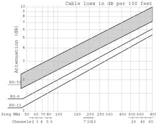
Alternatively, you can just use the diagram in Figure 4-2.
For example, suppose 10 feet of cable loses 1dB of signal. To figure the loss in a longer cable, just add 1dB for every 10 feet. In general, decibels let you add or subtract instead of multiply or divide. There are also some specific decibel markers, and the effect they have on gain, that you might want to memorize:
20dB = gain factor of 100
10dB = gain factor of 10
3dB = gain factor of 2 (actually 1.995)
0dB = no gain or loss
–1dB = a 20% loss of signal
–3dB = a 50% loss of signal
10dB = a 90% loss of signal
Whether a signal is receivable is determined by the signal-to-noiseratio. For TVs there are two main sources of noise.
- Atmospheric noise
This noise can come from many different types of sources. For example, a light switch creates a radio wave every time it's turned on or off. As another example, motors in some appliances produce nasty RF (radio frequency) noise.
- Receiver noise
Most of this noise comes from the first transistor the antenna is attached to. Some receivers are quieter than others.
Receiver noise dominates on the VHF and UHF bands, and atmospheric noise is usually insignificant. On an analog channel, noise looks like snow. If there is only a barely perceptible amount of snow, it corresponds to how noise-free a DTV signal must be for a DTV receiver to lock on to it.
Many people think that connecting an external amplifier to the antenna can improve the performance of the antenna. Unfortunately, this is usually wrong.
The signal-to-noise ratio is generally set by the receiver's first transistor. But if an external amplifier is added, the first transistor in the (added) amplifier determines the signal-to-noise ratio.
Tip
Because the signal and the external amp's noise are magnified greatly, the receiver's noise becomes insignificant.
Because there is no reason to think the external amp's first transistor is quieter than the receiver's first transistor, there is generally no benefit to the signal-to-noise ratio from an external amplifier.
However—and here's the good news—an external amplifier can compensate for signal loss in the cable if the amplifier is mounted at the antenna. Without this amplifier, a weak signal, just higher than the noise level at the antenna, could sink lower than the noise level due to loss in the cable, and be useless at the receiver.
RG-6 cable loses 1dB of the signal every 18 feet at channel 52. For a DTV channel, 1dB can be the difference between dropouts every 15 minutes (probably acceptable) and every 30 seconds (unwatchable). I recommend a mast-mounted amplifier whenever the cable length exceeds 20 feet.
Tip
If you are in a good-signal area or you have no high-numbered UHF channels, you can, to an extent, ignore this advice.
The amplifier should have a gain equal to the loss in the cable (for your highest channel) plus another 10dB (to keep the receiver's first transistor out of the picture). You generally can overshoot this target by 10dB without causing any trouble.
When figuring the cable loss, be sure to include the loss in any splitters and baluns. If a 2-to-1 splitter were 100% efficient, you would figure a 3dB loss because each TV gets half of the power. More realistically, splitters are usually 80% to 90% efficient.
The antenna and the amplifier both have gains measured in dB, and many people add these two numbers (and then maybe subtract the losses) to find the strength of the signal at the receiver. However, this calculation has little real value; you always should keep the net gain in front of the amplifier separate from the net gain that follows.
Actually there is a reason to think the external amplifier is quieter than the receiver is. Long ago, designers made an effort to make the TV's first amplifier stage very quiet. But now 90% of homes use cable or satellite boxes (strong sources) and most of the rest are rural homes using antennas that have mast-mounted amplifiers. So, the TV's noise is rarely a factor. Many TV makers no longer put any effort into making their sets quiet.
Suppose you live in an apartment 15 miles from the transmitter of the signal you're trying to capture. Your indoor antenna mostly works, but you are troubled by dropouts. Will adding an amplifier right at the TV improve things? Yes, if it is quieter than the TV. Unfortunately, TV makers see no reason to publish the noise figures for their receivers. So, buying an amplifier for an indoor antenna is a total crapshoot. I recommend that you try a Channel Master Titan or Spartan amplifier, but make sure you can return it if it is of no help.
Twinlead (ribbon cable) used to be common for connecting TVs to antennas, and it does have its advantages. However due to its unpredictability when positioned near metal or dielectric objects, it has fallen out of favor.
Tip
Such objects, even if not touching the cable, cause a portion of the signal to bounce, return to the antenna, and get retransmitted.
Coaxial cable is recommended instead. It's fully shielded and not affected by nearby objects. Coaxial cable has a feature called characteristic impedance, which for TVs always should be 75 ohms.
Although rated in ohms, this measurement has nothing to do with resistance. A resistor converts electric energy into heat. The "75 ohms" of a coaxial cable don't cause heat. Where it comes from is mathematically complicated, and beyond our scope here.
But coax also has ordinary resistance (mostly in the center conductor: see Table 4-4) and thus loses some of the signal, converting it into heat. The amount of this dissipation (loss) depends on the frequency as well as the cable length.
Table 4-4. Cable diameter and center conductivity
|
Type of cable |
Center conductor |
Cable diameter |
|---|---|---|
|
RG-59 |
20–23 gauge |
0.242 inches |
|
RG-6 |
18 gauge |
0.265 inches |
|
RG-11 |
14 gauge |
0.405 inches |
The cable loss is shown pictographically in Figure 4-3.
The table in Figure 4-3 is only approximate. There are many cable manufacturers for each type, and there is no enforcement of standards. If the mast-mounted amplifier gain exceeds the cable loss, it shouldn't matter what cable type you use. But there are two problems with this.
Some cable has incomplete shielding. This is most common for RG-59 and is another reason to avoid it.
When the cable run is longer than 200 feet, the low-numbered channels can become too strong relative to the high-numbered channels. In this case, RG-11 or an ultra-low-loss RG-6 is recommended (these alternatives are expensive). Alternatively, frequency-compensated amplifiers will work.
I usually recommend RG-6 for all TV antennas. It can be stapled in place using a staple gun with common 9/16-inch T25 staples. How long the cable lasts depends solely on how long you can keep water out of it. 3M Vinyl Electrical Tape is a good waterproofer. Even better is an asphalt putty called "Coax Seal" (RadioShack 278-1645), but it is so tenacious it should not be used for temporary connections. Cover the connectors completely.
Signal amplifiers are supposed to be linear. That is, the output is a magnified but otherwise unaltered version of the input. But too much signal can make an amplifier nonlinear, usually clipping off the tops and bottoms of the sine waves. When this happens, all channels are affected, not just the one that is too strong. In fact, the too-strong signal usually is not a TV station. A close FM station or police station is more likely.
If you add a good amplifier to your antenna system and your results get worse instead of better, you have overload, and you need to reconsider more carefully what you are doing.
An attenuator is a resistor network that can reduce the gain of an amplifier; 6dB attenuators are available at RadioShack. Insert the attenuator between the TV and the power injector. If you are close to an FM station, there might be a narrow range between too much and too little gain. You can make that range larger by using an amplifier with an FM trap or by using a more directional antenna.
First, you'll need to have some more basic terms under your belt.
This is the simplest TV antenna. Variations on the dipole are the bowtie (which has wider bandwidth), the folded dipole (which can solve an efficiency problem), and the loop (a variation on the folded dipole). All four have the same gain and the same radiation field: a toroid (doughnut shape: see Figure 4-4). The gain is generally 2.15dBi, which means "dB of improvement over an isotropic radiator." That's a lot of verbiage that simply means an antenna that radiates equally in all directions.
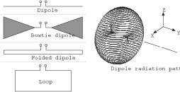
The dipole has positive gain because it doesn't radiate equally in all directions. This is a universal truth. To get more gain, an antenna must radiate in fewer directions. Imagine a spherical balloon. Now press on it from opposite sides with a finger of each hand. Push in until your fingers meet. The result looks like the toroid, as in Figure 4-4. But more important, the balloon expanded in the other directions. Aha! Gain! That's the way antennas work.
Keep this balloon analogy in mind. More complicated antennas work by reducing radiation in most directions. They distort the balloon considerably, but the volume of the balloon remains constant.
Another rating system for antennas uses dBd, which means "dB of improvement over a dipole antenna." To convert dBd to dBi, just add 2.15. Antenna makers specify their gains in dB. They actually mean dBd, but given the way they exaggerate their claims, dBi is usually closer to the truth.
In the United States, TV antennas are always horizontal. If you rotate an antenna about the forward axis (a line from the transmitting antenna) the signal strength will vary as the cosine of the angle. In other words, when the antenna elements are vertical, no signal is received because TV signals have horizontal polarization.
Two heads are better than one, and so it is with dipoles. N dipoles will take in N times as much RF power as one dipole, provided they are not too close to each other. Thus, a four-dipole antenna would have a gain of 8.15dBi. (That is 2.15dBi doubled once [plus 3dB] and doubled again [plus another 3dB].) This assumes their positions and cable lengths are adjusted so that their signals add in-phase. This explanation of gain might seem at odds with the balloon explanation, but ultimately they are equivalent.
Tip
Adding dipoles doesn't increase the volume of the balloon because phase cancellation occurs in some directions.
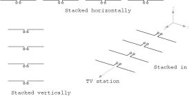
Dipoles are commonly stacked horizontally (collinearly), vertically (broadside), and in echelon (end-fire). Figure 4-5 shows examples of all three configurations.
When dipoles are stacked horizontally, the horizontal beamwidth becomes very narrow. This is because they don't add in-phase for directions that are not straight ahead. Similarly, when stacked vertically, the vertical beam-width becomes narrower.
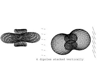
Let's say you are 20 miles from a city, and TV transmitters are scattered all over the city. A medium-gain antenna might be too weak, but a high-gain antenna would be so directional you'd need a rotor. Solution: a bunch of dipoles stacked vertically can give you the gain you need (as illustrated in Figure 4-6). The vertical narrowness of the resulting beam is of little importance, but the horizontal broadness of the beam means no rotor is needed.
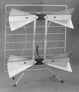
Radio waves reflect off a large conducting plane as if it were a mirror. A coarse screen can serve as well. Reflector antennas are very common. The double bowtie in Figure 4-7 has gain of 5–7dBi. With a bigger screen, it would have more.
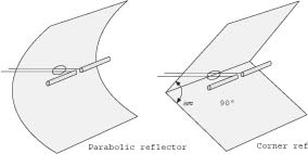
The parabolic reflector shown in Figure 4-8 focuses the signal onto a single dipole, but its bandwidth is a little disappointing. The corner reflector (in the same figure) has a little less gain but much greater bandwidth. The corner reflector has roughly the gain of three dipoles. It is a good medium-gain antenna, widely used for UHF.
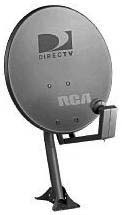
If you need more than 25dBi, the paraboloid dish shown in Figure 4-9 is the only practical choice.
The LPDA, shown in Figure 4-10, has several dipoles arranged in echelon and crisscross-fed from the front. The name comes from the geometric growth, which is logarithmic.
This is a very wide-band antenna with a gain of up to about 7dBi. For any frequency, only about three of the elements are carrying much current. The other elements are inactive. As frequency increases, the active elements "move" toward the front of the array. Most VHF antennas are LPDAs.
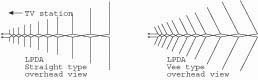
TV LPDAs come in two types: straight and Vee. The Vee type has just a slightly higher gain for channels 7–13. But I usually favor the straight type because it has nulls 90° to each side that can be used to cancel out ghosts.
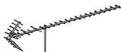
A Yagi antenna has several elements arranged in echelon. They are connected together by a long element, called the boom. The boom carries no current. If the boom is an insulator, the antenna works the same. Figure 4-11 shows the overhead view of a Yagi antenna.
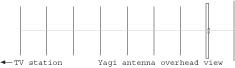
The rearmost element is called the reflector. The next element is called the driven element. All the remaining elements are called directors. The directors are about 5% shorter than the driven element. The reflector is about 5% longer than the driven element. The driven element is usually a folded dipole or a loop. It is the only element connected to the cable. Yet the other elements carry almost as much current.
The Yagi is the most magical of all antennas. I won't attempt to explain why it works; the math simply gets way too complex. Suffice it to say that the more directors you add, the higher the gain becomes, and gains higher than 20dBi are possible. But the Yagi is a narrow-band antenna, often intended for a single frequency. As frequency increases above the design frequency, the gain declines abruptly. Below the design frequency, the gain falls off more gradually. When a Yagi is to cover a band of frequencies, it must be designed for the highest frequency of the band.
A UHF Yagi today is designed for channel 69. If you see an old Yagi, it might be intended for channel 82. In the future they will be cut for channel 51. It's not possible to tell by looking at a Yagi which era it belongs to, so be careful. Often the reflector element is replaced by a corner reflector, as shown in Figure 4-12.
This corner reflector makes up somewhat for the poor performance on the lower-numbered channels. Although the Yagi/Corner-Reflector is not the best antenna, it is the most common UHF TV antenna, mainly because it can be mounted on the front of a VHF antenna without degrading the VHF antenna.
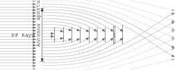
An antenna also has an aperture area, from which it captures all incoming radiation. The aperture of a Yagi is round (see Figure 4-13) and its area is proportional to the gain. As the leading elements absorb power, diffraction bends the adjacent rays in toward the antenna.
The graph in Figure 4-14 shows the gain functions for four TV antennas:
Plot A is the Channel Master 4228 8-Bay, a stacked dipole reflector antenna.
Plot B is the Channel Master 4248, a Yagi/Corner-Reflector.
Plot C is the 4248 with all of its directors removed, making it a pure corner reflector antenna.
Plot D is the 4248 with its corner reflector removed and replaced by a single reflector element, making it a standard Yagi. The D2 plot shows the backward gain where this exceeds the forward gain.
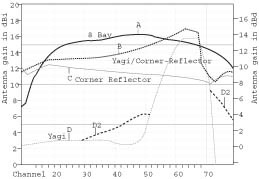
The point of this graph is that a Yagi/Corner-Reflector performs like a Yagi for the high-numbered channels, and like a corner reflector for the low-numbered channels. For the middle channels it outperforms the sum of the two types. Clearly, the 8-Bay and Yagi/Corner-Reflector are the favorites here.
The last thing to be aware of is the radiation patterns of these antennas. First, Figure 4-15 is the overhead view of an 8-Bay antenna.
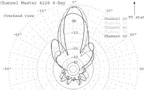
Figure 4-16 is the elevation view of the same antenna.
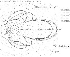
As you can see, the 8-Bay is a very directional antenna. If the aim is off by 5°, you can lose 1dB of signal. If the horizon is more than 5° above horizontal, you should tilt the antenna up to point at the horizon.
The overhead view shows nulls at 30° and 90° to both sides. These can be used to eliminate multipath (ghosts) or interference. You simply rotate the antenna until the offending signal is in one of the nulls.
Compare that to Figure 4-17, the overhead view of a Yagi/Corner-Reflector antenna.
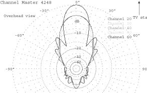
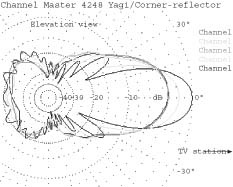
Figure 4-18 is the aerial view of the Yagi/Corner-Reflector.
A Yagi also has some forward nulls that can be used as ghost killers. But a Yagi/Corner-Reflector acts more like a corner reflector for most channels, and has no nulls. At channel 60 you can finally see the Yagi pattern start to emerge.
I prefer the 8-Bay to the Yagi/Corner-Reflector for the following reasons:
It has high gain.
Its gain is evenly distributed over the channels.
It has nulls that can eliminate multipath.
It has a rectangular aperture that permits efficient stacking when more than eight bays are necessary [Hack #81] .
However, the high gain means it is hard to aim. In good-signal areas, avoid high-gain antennas.
Antenna marketing is a racket in that the less honest you are, the more antennas you sell. Gain figures published by antenna makers are mostly useless, except maybe for comparing antennas by the same maker. The data for all the charts in this section came from computer simulations of the antennas that I performed.
Raw gain is the true gain of an antenna—using the"pure" definition of gain (as seen in Figure 4-19).
However, a fraction of the power is going to be rejected by the transmission line because of an impedance mismatch. This rejected power gets retransmitted. What is left is the net gain. Therefore, the graph in Figure 4-20 is the one you should pay the most attention to.
Here's the legend for both graphs:
B: Channel Master 4221 4-Bay
C: Channel Master 4248 Yagi/Corner-Reflector
F: Winegard PR-4400 4-Bay
G: Channel Master 4242 VHF/UHF Combo
H: Channel Master 3018 VHF/UHF Combo
J: Small indoor loops
K: Double-Bow
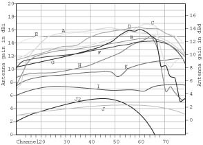
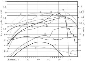
Some of these antennas are UHF-only. Although you might not need VHF presently, you probably will after 2006.
The 4242 and 3018 represent typical Yagi/Corner-Reflector UHF antennas that are part of a VHF/UHF combo. You can estimate any other unknown such antenna from these two. Just find the length of the UHF part of the boom of the unknown antenna (measured from the intersection of the corner planes to the frontmost director). Compare this length to the 4242 and 3018 to estimate where the plot for the unknown lies in the preceding graph. The 4242 has an 87-inch boom; the 3018 has a 57-inch boom.
Here are the same graphs, but for common VHF antennas. Figure 4-21 shows the raw gain for common VHF antennas.
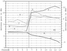
Figure 4-22 is the net gain for these VHF antennas.
Here's the legend:
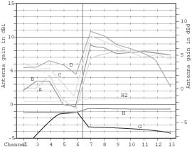
If all the elements are parallel (as in a straight-type LPDA), there will be nulls at +90° and –90° that might be useful for eliminating ghosts and interfering signals.
I realize that's a lot of information, but I'd rather you make an informed decision than just take my word for it (or, even worse, some salesperson's opinion). With these graphs and the other information in this hack, you should easily be able to determine which antenna is best for your house, location, and broadcasting needs.
—Kenneth L. Nist
Get Home Theater Hacks now with the O’Reilly learning platform.
O’Reilly members experience books, live events, courses curated by job role, and more from O’Reilly and nearly 200 top publishers.

