8.1 The Components and Calculations of the RF Link
Let us try to break down the link budget and have a look on the most important parameters in the calculation. The simplest LB calculation looks, in principle, like this:
![]()
However, the real-life GSM and UMTS LB are more complex, so you will need to break down the link budget calculation into more detail.
8.1.1 The Maximum Allowable Path Loss
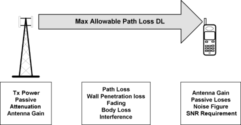
The essential purpose of making the link budget is to calculate the maximum allowable path loss, as shown in Figure 8.1. Once you have calculated the APL, you can calculate the service area and service radius to use for antenna placement in the building.
Figure 8.1 Principles of the link budget (DL)

Note that the example in Figure 8.1 is rather simplified, and merely shows a few of the factors you need to take into account when calculating the link budget. This simplified example shows only the downlink, but both the downlink and the uplink APL need to be calculated, for all services on the DAS.
8.1.2 The Components in the Link Budget
In order to understand the details in the link budget for indoor DAS design, you need to break it down to the all various components of gains and losses. Then you can understand how the different parameters interact and affect the link budget calculation.
The components ...
Get Indoor Radio Planning: A Practical Guide for GSM, DCS, UMTS, HSPA and LTE, Second Edition now with the O’Reilly learning platform.
O’Reilly members experience books, live events, courses curated by job role, and more from O’Reilly and nearly 200 top publishers.

