Neighbor discovery (ND) is specified in RFC 2461 (obsoletes RFC 1970). The specifications in this RFC relate to different protocols and processes known from IPv4 that have been modified and improved. New functionality has also been added. It combines Address Resolution Protocol (ARP) and ICMP router discovery and Redirect. With IPv4, we have no means to detect whether or not a neighbor is reachable. With the neighbor discovery protocol, a neighbor unreachability detection mechanism has been defined. Duplicate IP address detection has been implemented, too. IPv6 nodes use neighbor discovery for the following purposes:
To determine layer 2 addresses of nodes on the same link
To find neighboring routers that can forward their packets
To keep track of which neighbors are reachable and which are not, and detect changed link-layer addresses
The following improvements over the IPv4 set of protocols can be noted:
Router discovery is now part of the base protocol set. With IPv4, the mechanism needs to get the information from the routing table.
Router advertisement packets contain link-layer addresses for the router. There is no need for the node receiving a Router Advertisement to send out an additional ARP request (as an IPv4 node would have to do) to get the link-layer address for the router interface. The same is true for ICMPv6 redirect messages; they contain the link-layer address of the new next-hop router interface.
Router advertisement packets contain the prefix for a link (subnet information). There is no need to configure subnet masks anymore. They can be learned from the Router Advertisement.
Neighbor discovery provides mechanisms to renumber networks easily. New prefixes and addresses can be introduced and old ones can be deprecated and removed.
Router advertisements enable stateless address autoconfiguration and can notify hosts when to use stateful address configuration (e.g., DHCP).
Multiple prefixes can be assigned to one link. By default, hosts learn all prefixes from the router, but the router can be configured not to advertise some or all of the prefixes. In that case, hosts assume that a non-advertised prefix destination is remote and send the packets to the router. The router can then issue ICMP redirect messages as needed.
Neighbor unreachability detection is part of the base protocol. It substantially improves packet delivery in case of failed routers or link interfaces that changed their link-layer address. It solves the issues with outdated ARP caches. ND detects failed connectivity and traffic is not sent to neighbors that are unreachable. The neighbor unreachability detection also detects failed routers and switches to live ones.
Router advertisements and ICMP redirects use link-local addresses to identify routers. This allows hosts to maintain their router associations even in the case of renumbering or use of new global prefixes.
Neighbor discovery messages have a hop limit value of 255, and requests with a lower hop limit are not answered. This makes Neighbor discovery immune to remote hosts that try to sneak into your link because their packets have decremented hop limit and are thus ignored.
The neighbor discovery protocol is used to detect duplicate IP addresses on a link.
Standard IP authentication and security mechanisms can be applied to neighbor discovery.
This summary gives an idea of what can be expected from this part of the specification. Now let’s discuss the different processes in detail. The neighbor discovery protocol consists of five ICMP messages: a pair of Router Solicitation/Router Advertisement messages, a pair of Neighbor Solicitation/Neighbor Advertisement messages, and an ICMP redirect message (refer to Table 4-2, earlier in this chapter, for a summary of ICMP informational message types).
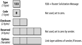
Routers send out Router Advertisement messages in regular intervals. Hosts can request Router Advertisements by issuing a Router Solicitation message. This will trigger routers to issue Router Advertisements immediately, outside of the regular interval. The format is shown in Figure 4-10.
In the IP header of a Router Solicitation message, you will usually
see the
all-routers
multicast address of FF02::2 as a destination
address. The hop limit is set to 255. The ICMP
Type field is set to 133, which is the value for the Router
Solicitation message. The Code field is unused and set to 0. The
following two Bytes are used for the
Checksum. The next
four Bytes are unused and reserved for future use. The sender sets
them to 0 and the receiver ignores those fields. For a Router
Solicitation message, valid Options are the link-layer address of
the sending host, if known. If the source address on the IP layer is
the unspecified (all-zeros) address, this field is not used.
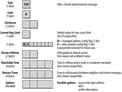
Routers that receive this Solicitation message reply with a Router Advertisement message. Routers also issue those messages periodically. The format of the Router Advertisement message is shown in Figure 4-11.
By inspecting the IP header of the Router Advertisement message, you
can determine whether this Router Advertisement is periodic or was
sent in reply to a Solicitation message. A
periodic
advertisement’s destination address will be the
all-nodes multicast address FF02::1. A solicited
advertisement’s destination address will be the
address of the interface that originated the solicitation message.
Again, the hop limit is set to 255.
The ICMP Type field is set to 134, the value for a Router Advertisement message; the Code field is unused and set to 0. The Current Hop Limit field can be used to configure all nodes on a link for a default hop limit. The value entered in this field will be used as a default hop limit value in outgoing packets by all nodes on the link. A value of 0 in this field means that this option is unspecified by this router—in which case, the default hop limit values of the source hosts are used.
The next 1-bit field, the M flag, specifies whether stateful configuration is to be used. Stateful configuration refers to what we know as DHCP with IPv4. If this bit is 0, the nodes on this link use autoconfiguration. If the bit is set to 1, it specifies stateful configuration. The O flag configures whether nodes on this link use stateful configuration for other than IP address information. A value of 1 means the nodes on this link use stateful configuration for non-address-related information. The remaining 6 bits of this byte are reserved for future use and must be 0.
The Router Lifetime field is important only if this router is to be used as a default router by the nodes on the link. A value of 0 indicates that this router is not a default router and will therefore not appear on the default router list of receiving nodes. Any other value in this field specifies the lifetime, in seconds, associated with this router as a default router. The maximum value is 18.2 hours.
The Reachable Time field is the time in which a host assumes that neighbors are reachable after having received a reachability confirmation. A value of 0 means unspecified. The neighbor unreachability detection algorithm uses this field.
The Retrans Timer field is used by the address resolution and neighbor unreachability detection mechanisms; it states the time in milliseconds between retransmitted Neighbor Solicitation messages.
For the Options field, there are currently three possible values: source link-layer address, MTU size to be used on links with variable MTU sizes (Token Ring, for example), and prefix information. This field is important for autoconfiguration. The router inserts all its prefixes for the link that the nodes on the link need to know.
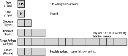
This pair of messages fulfills two functions: the link-layer address resolution that is handled by ARP in IPv4 and the neighbor unreachability detection mechanism. If the destination address is a multicast address, the source is resolving a link-layer address. If the source is verifying the reachability of a neighbor, the destination address is a unicast address. This message type is also used for duplicate IP address detection (DAD). The format of the Neighbor Solicitation message is shown in Figure 4-12.
In the IP header of this message type, the source address can be either the interface address of the originating host or, in the case of DAD, the unspecified (all-zeros) address. The hop limit is set to 255. The Type field in the ICMP header is set to 135, and the Code field is unused and set to 0. After the two checksum bytes, four unused bytes are reserved and must be set to 0. The target address is used only in messages that are used for unreachability detection and DAD. It must not be a multicast address.
The Options field can contain the link-layer source address. It contains a link-layer address only if it is not a DAD message. In a DAD message that uses the unspecified address as a source address, the options field is set to 0. The link-layer option must be used in multicast solicitations (neighbor discovery and ARP functionality) and should be used in unicast solicitations (unreachability detection).
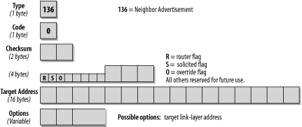
Neighbor Advertisement messages are sent as a reply to Neighbor Solicitation messages or to propagate new information quickly. The format of the message is shown in Figure 4-13.
The type of address in the IP header indicates whether the message is
the answer to a solicitation or an unsolicited message. In case of a
solicited advertisement, the
destination IP address is the source address of the interface that
sent the solicitation. If the message is the reply to a DAD message
that originated from an unspecified source address, the reply will go
to the all-nodes multicast address of FF02::1. The
same is true for all unsolicited periodic
advertisements.
The Type field in the ICMP header is set to 136, the value for Neighbor Advertisement messages. The Code field is unused and set to 0. When the Router flag is set, the sender is a router.
When the Solicited flag is set, the message is sent in response to a Neighbor Solicitation. For instance, if a host confirms its reachability in answer to a unreachability detection message, the S bit is set. The S bit is not set in multicast advertisements. The Override flag indicates that the information in the Advertisement message should override existing neighbor cache entries and update any cached link-layer addresses. If the O bit is not set, the advertisement will not update a cached link-layer address, but it will update an existing neighbor cache entry for which no link-layer address exists. The O bit should not be set in an advertisement for an anycast address. The cache entries are discussed later in this chapter. The remaining 29 bits are reserved for future use and set to 0.
In solicited advertisements, the Target Address contains the address of the interface that sent the solicitation. In unsolicited advertisements, this field contains the address of the interface whose link-layer address has changed. A possible option for the Options field is the target link-layer address.
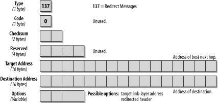
Routers issue ICMP Redirect messages to inform a node of a better first-hop node on the path to a given destination. A Redirect message can also inform a node that the destination used is in fact a neighbor on the same link and not a node on a remote subnet. The format of the ICMPv6 Redirect message is shown in Figure 4-14.
The source address in the IP header must be the link-local address of the interface from which the message is sent. The destination address in the IP header is the source address from the packet that triggered the redirect message. The hop limit is set to 255.
The Target Address field contains the link-local address of the interface that is a better next-hop to use for the given destination address. The Destination Address field contains the address of the destination that is redirected, which should be used to get to the destination address. If the address in the Target Address field is the same as the address in the Destination Address field, the destination is a neighbor and not a remote node. The Option field contains the link-layer address for the target (the best next-hop router). This is an improvement on the IPv4 version, in which the host needed to issue a separate ARP request to determine the link-layer address of the next-hop router.
Neighbor discovery messages contain a variable-size Options field that has the format shown in Figure 4-15.
The Type field indicates what type of option follows. The following types are defined in RFC 2461:
Type 1: source link-layer address
Type 2: target link-layer address
Type 3: prefix information
Type 4: redirected header
Type 5: MTU
The Length field indicates the length of the option. Value 0 is invalid for this field, and packets with this value must be discarded. The calculation of the length includes the Type and Length fields.
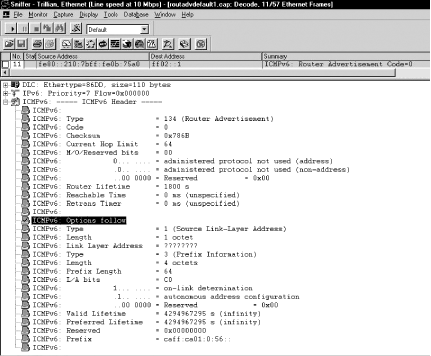
The screenshot in Figure 4-16 shows the details of a Router Advertisement with two Option fields. This trace file was taken when we had just set up our router. Besides initializing the IPv6 stack and configuring it for the prefix, we have not changed any of the configuration parameters. The options used in this case are option 1 (source link-layer address) and option 3 (prefix information). Note the format of the Option fields.
The Type field is set to 134, the value for a Router Advertisement. The Current Hop Limit has a value of 64. All nodes on this link will use this value for their Hop Count field. The M and O flags are not set by default. The Router Lifetime is set to 1800, which also indicates that this is a default router. The first Option listed is type 1. The link-layer address in the detail screen shows a lot of question marks, but don’t worry about them. The link-layer address of the router can be seen in the hex part of the window (not shown in the screenshot); it is just not decoded in the detail window. The second Option is of type 3 for prefix information. Note all the additional information that can be given with a prefix. The Prefix Length field specifies the number of bits valid for the prefix (i.e., the length of the subnet mask). The L bit is the on-link flag. If set, it indicates that this prefix can be used for on-link determination. If it is not set, the advertisement does not make a statement and the prefix can be used for on-link and off-link configuration. The A-bit is the autonomous address configuration flag. If set, it indicates that the prefix can be used for autonomous address configuration. In this case, the host will generate an address by adding the interface identifier to the prefix or, if the privacy options are used, by adding a random number. The Valid Lifetime field specifies how long this prefix is valid. A value of all F means infinity. The Preferred Lifetime specifies how long the address being configured with this prefix can remain in the preferred state. Again, a value of all F means infinity.
IPv6 nodes need to maintain different tables of information. Among these tables, the neighbor cache and destination cache are particularly important. Depending on the IPv6 stack you are working with, the implementation and the troubleshooting utilities will be different. But the information must be available on every IPv6 node.
- Neighbor cache
The neighbor cache maintains a list of neighbors to which traffic has been sent recently. They are listed by their unicast IP address, and each entry contains information about the neighbor’s link-layer address and a flag that indicates whether the neighbor is a router or host. This can be compared to the ARP cache in an IPv4 node. The entry also contains information about whether there are packets queued to be sent to that destination, information about the neighbor’s reachability, and the time the next neighbor unreachability detection event is scheduled to take place.
- Destination cache
This table maintains information about destinations to which traffic has been sent recently, including local and remote destinations. The neighbor cache can be seen as a subset of destination cache information. In case of remote destinations, the entry lists the link-layer address of the next-hop router. The destination cache is updated with information received by ICMP Redirect messages. It can also contain additional information about MTU sizes and roundtrip timers.
The neighbor cache and destination cache have been mentioned in regard to the Override flag that can be set in a Neighbor Advertisement message. If the Override flag is set, the information in the Advertisement message should override existing neighbor cache entries and update any cached link-layer addresses in the cache of the host that receives the advertisement. If the O bit is not set, the advertisement will not update a cached link-layer address, but will update an existing neighbor cache entry for which no link-layer address exists.
The screenshot in Figure 4-17 shows the neighbor cache entries of our Cisco router. There were two hosts on the link at the time the screenshot was taken.
A neighbor cache entry can be in one of five states, according to RFC 2461. The five states are explained in Table 4-6.
Table 4-6. States of neighbor cache entries
Get IPv6 Essentials now with the O’Reilly learning platform.
O’Reilly members experience books, live events, courses curated by job role, and more from O’Reilly and nearly 200 top publishers.
