To provide the high-density and high-speed Ethernet services, a new type of Flexible Port Concentrator (FPC) had to be created called the Dense Port Concentrator (DPC). This first-generation line card allowed up to 80 Gbps ports per slot.
The DPC line cards utilize a previous ASIC from the M series called the I-CHIP. This allowed Juniper to rapidly build the first MX line cards and software.
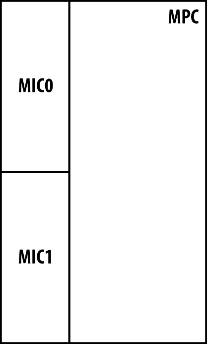
The Modular Port Concentrator (MPC) is the second-generation line card created to further increase the density to 160 Gbps ports per slot. This generation of hardware is created using the Trio chipset. The MPC supports MICs that allow you to mix and match different modules on the same MPC.
Table 1-5. Juniper MX line card and module types
FPC Type/Module Type | Description |
|---|---|
Dense Port Concentrator (DPC) | First-generation high-density and high-speed Ethernet line cards |
Modular Port Concentrator (MPC) | Second-generation high-density and high-speed Ethernet line cards supporting modules |
Module Interface Card (MIC) | Second-generation Ethernet and optical modules that are inserted into MPCs |
It’s a common misconception that the “modular” part of MPC derives its name only from its ability to accept different kinds of MICs. This is only half of the story. The MPC also derives its name from being able to be flexible when it comes to the Trio chipset. For example, the MPC-3D-16x10GE-SFPP line card is a fixed port configuration, but only uses the Buffering Block and Lookup Block in the PFE complex. As new line cards are introduced in the future, the number of fundamental Trio building blocks will vary per card as well, thus living up to the “modular” name.
The DPC line cards come in six different models to support varying different port configurations. There’s a mixture of 1G, 10G, copper, and optical. There are three DPC types: routing and switching (DPCE-R), switching (DPCE-X), and enhanced queuing (DPCE-Q).
The DPCE-R can operate at either Layer 3 or as a pure Layer 2 switch. It’s generally the most cost-effective when using a sparing strategy for support. The DPCE-R is the most popular choice as it supports very large route tables and can be used in a pure switching configuration as well.
The DPCE-X has the same features and services as the DPCE-R; the main difference is that the route table is limited to 32,000 prefixes and cannot use L3VPNs on this DPC. These line cards make sense when being used in a very small environment or in a pure Layer 2 switching scenario.
The DPCE-Q supports all of the same features and services as the DPCE-R and adds additional scaling around H-QoS and number of queues.
Table 1-6. DPC line card types
Model | DPCE-R | DPCE-X | DPCE-Q |
|---|---|---|---|
40x1GE SFP | Yes | Yes | Yes |
40x1GE TX | Yes | Yes | No |
20x1GE SFP | No | No | Yes |
4x10GE XFP | Yes | Yes | Yes |
2x10GE XFP | Yes | No | No |
20x1GE and 2x10GE | Yes | Yes | Yes |
Note
The DPC line cards are still supported, but there is no active development of new features being brought to these line cards. For new deployments, it’s recommended to use the newer, second-generation MPC line cards. The MPC line cards use the Trio chipset and are where Juniper is focusing all new features and services.
The MPC line cards are the second generation of line cards for the MX. There are two significant changes when moving from the DPC to MPC: chipset and modularity. All MPCs are now using the Trio chipset to support more scale, bandwidth, and services. The other big change is that now the line cards are modular using MICs.
The MPC can be thought of as a type of intelligent shell or carrier for MICs. This change in architecture allows the separation of physical ports, oversubscription, features, and services. All of the oversubscription, features, and services are managed within the MPC. Physical port configurations are isolated to the MIC. This allows the same MIC to be used in many different types of MPCs depending on the number of features and scale required.
As of Junos 11.4, there are three different categories of MPCs. Each model has a different number of Trio chipsets providing different options of scaling and bandwidth.
Table 1-7. Modular port concentrator models
Model | # of Trio chipsets | Trio Bandwidth | Interface Support |
|---|---|---|---|
MPC1 | 1 | 40 Gbps | 1GE and 10GE |
MPC2 | 2 | 80 Gbps | 1GE and 10GE |
MPC3E | 1 | 130 Gbps | 1GE, 10GE, 40GE, and 100GE |
The MPC3 is the first of many more MPCs that will use an enhanced Trio chipset that is designed to support 40G and 100G interfaces. The MPC3 was designed to be similar to the MPC1 architecture whereby a single Trio chipset handles both MICs and is intentionally oversubscribed to offer an attractive price point.
Note
It’s important to note that the MPC bandwidth listed previously represents current-generation hardware that’s available as of the writing of this book and is subject to change with new software and hardware releases.
Similar to the first-generation DPC line cards, the MPC line cards also support the ability to operate in Layer 2, Layer 3, or enhanced queuing modes. This allows you choose only the features and services required.
Table 1-8. MPC feature matrix
Model | Full Layer 2 | Full Layer 3 | Enhanced Queuing |
|---|---|---|---|
MX-3D | Yes | No | No |
MX-3D-Q | Yes | No | Yes |
MX-3D-R-B | Yes | Yes | No |
MX-3D-Q-R-B | Yes | Yes | Yes |
Most Enterprise customers tend to choose the MX-3D-R-B model as it supports both Layer 2 and Layer 3. Typically, there’s no need for enhanced queuing or scale when building a data center. Most Service Providers prefer to use the MX-3D-Q-R-B as it provides both Layer 2 and Layer 3 services in addition to enhanced queuing. A typical use case for a Service Provider is having to manage large routing tables, many customers, and provide H-QoS to enforce customer service level agreements (SLAs).
The MX-3D-R-B is the most popular choice, as it offers full Layer 3 and Layer 2 switching support.
The MX-3D has all of the same features and services as the MX-3D-R-B but has limited Layer 3 scaling. When using BGP or an IGP, the routing table is limited to 32,000 routes. The other restriction is that MPLS L3VPNs cannot be used on these line cards.
The MX-3D-Q has all of the same features, services, and reduced Layer 3 capacity as the MX-3D, but offers enhanced queuing. This adds the ability to configure H-QoS and increase the scale of queues.
The MX-3D-Q-R-B combines all of these features together to offer full Layer 2, Layer 3, and enhanced queuing together in one line card.
Let’s revisit the MPC models in more detail. The MPC starts off with the MPC1, which has a single Trio chipset. The use case for this MPC is to offer an intelligently oversubscribed line card for an attractive price. All of the MICs that are compatible with the MPC1 have the Interfaces Block built into the MIC to handle oversubscription.
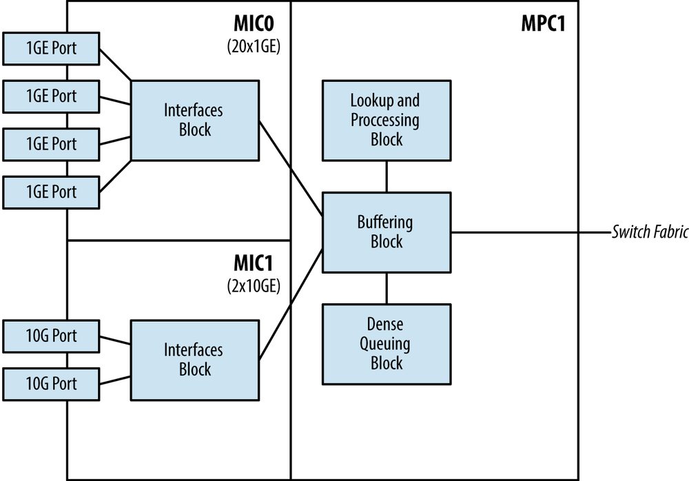
With the MPC1, the single Trio chipset handles both MICs. Each MIC is required to share the bandwidth that’s provided by the single Trio chipset, thus the Interfaces Block is delegated to each MIC to intelligently handle oversubscription. Because each Trio chipset can only operate in MAC mode or UPOH mode, the MPC1 must operate in MAC mode to be able to support the 20x1GE and 2x10GE MICs. Unfortunately, the 4x10GE MIC only operates in UPOH mode and isn’t compatible with the MPC1.
The MPC2 is very similar in architecture to the MPC1, but adds an additional Trio chipset for a total count of two.
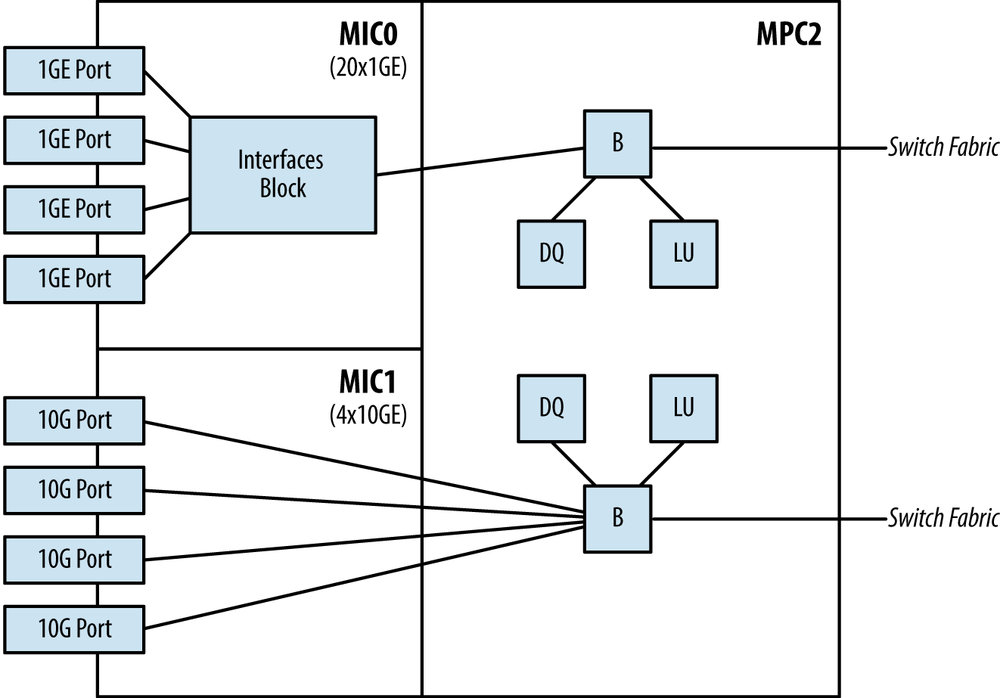
The MPC2 offers a dedicated Trio chipset per MIC, effectively doubling the bandwidth and scaling from the previous MPC1. In the MPC2 architecture example, it’s possible to combine MICs such as the 2x10GE and 4x10GE. Figure 1-23 illustrates the MPC2 being able to operate in both MAC mode and UPOH mode. Please note that Figure 1-23 uses several abbreviations:
B = Buffering Block
LU = Lookup Block
DQ = Dense Queuing Block
The 2x10GE MIC is designed to operate in both the MPC1 and MPC2 and thus has an Interfaces Block to handle oversubscription. In the case of the 4x10GE MIC, it’s designed to only operate in the MPC2 and thus doesn’t require an Interfaces Block as it ties directly into a dedicated Buffering Block.
The MPC-3D-16X10GE-SFPP is a full-width line card that doesn’t support any MICs. However, it does support 16 fixed 10G ports. This MPC is actually one of the most popular MPCs because of the high 10G port density and offers the lowest price per 10G port.
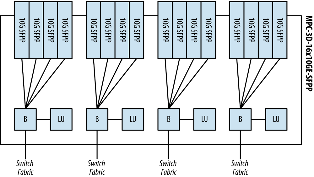
The MPC-3D-16X10GE-SFPP has four Trio chipsets equally divided between the 16 ports. This allows each group of 4x10G interfaces to have a dedicated Trio chipset. This enables the MPC-3D-16X10GE-SFPP to operate at line rate for all ports.
If you’re ever curious how many PFEs are on a FPC, you can use
the show chassis fabric map
command.
First, let’s find out which FPC the MPC-3D-16X10GE-SFPP is installed into.
dhanks@MX960> show chassis hardware | match 16x
FPC 3            REV 23   750-028467   YJ2172            MPC 3D 16x 10GE
We found what we were looking for. The
MPC-3D-16X10GE-SFPP is installed into FPC3. Now let’s take a peek at
the fabric map and see which links are Up, thus detecting the presence of PFEs
within FPC3.
dhanks@MX960> show chassis fabric map | match DPC3
DPC3PFE0->CB0F0_04_0    Up         CB0F0_04_0->DPC3PFE0    Up
DPC3PFE1->CB0F0_04_1    Up         CB0F0_04_1->DPC3PFE1    Up
DPC3PFE2->CB0F0_04_2    Up         CB0F0_04_2->DPC3PFE2    Up
DPC3PFE3->CB0F0_04_3    Up         CB0F0_04_3->DPC3PFE3    Up
DPC3PFE0->CB0F1_04_0    Up         CB0F1_04_0->DPC3PFE0    Up
DPC3PFE1->CB0F1_04_1    Up         CB0F1_04_1->DPC3PFE1    Up
DPC3PFE2->CB0F1_04_2    Up         CB0F1_04_2->DPC3PFE2    Up
DPC3PFE3->CB0F1_04_3    Up         CB0F1_04_3->DPC3PFE3    Up
DPC3PFE0->CB1F0_04_0    Up         CB1F0_04_0->DPC3PFE0    Up
DPC3PFE1->CB1F0_04_1    Up         CB1F0_04_1->DPC3PFE1    Up
DPC3PFE2->CB1F0_04_2    Up         CB1F0_04_2->DPC3PFE2    Up
DPC3PFE3->CB1F0_04_3    Up         CB1F0_04_3->DPC3PFE3    Up
DPC3PFE0->CB1F1_04_0    Up         CB1F1_04_0->DPC3PFE0    Up
DPC3PFE1->CB1F1_04_1    Up         CB1F1_04_1->DPC3PFE1    Up
DPC3PFE2->CB1F1_04_2    Up         CB1F1_04_2->DPC3PFE2    Up
DPC3PFE3->CB1F1_04_3    Up         CB1F1_04_3->DPC3PFE3    Up
That wasn’t too hard. The only tricky part is that the output of
the show chassis fabric command
still lists the MPC as DPC in the output. No worries, we can perform a
match for DPC3. As we can see, the MPC-3D-16X10GE-SFPP has a total of
four PFEs, thus four Trio chipsets. Note that DPC3PFE0 through DPC3PFE3 are present and listed as Up. This indicates that the line card in
FPC3 has four PFEs.
The MPC-3D-16X10GE-SFPP doesn’t support H-QoS because there’s no Dense Queuing Block. This leaves only two functional Trio blocks per PFE on the MPC-3D-16X10GE-SFPP: the Buffering Block and Lookup Block.
Let’s verify this by taking a peek at the preclassification engine:
dhanks@MX960> request pfe execute target fpc3 command "show precl-eng summary"
SENT: Ukern command: show prec sum
GOT:
GOT:  ID  precl_eng name       FPC PIC   (ptr)
GOT: --- -------------------- ---- ---  --------
GOT:   1 MQ_engine.3.0.16       3   0  4837d5b8
GOT:   2 MQ_engine.3.1.17       3   1  4837d458
GOT:   3 MQ_engine.3.2.18       3   2  4837d2f8
GOT:   4 MQ_engine.3.3.19       3   3  4837d198
LOCAL: End of file
As expected, the Buffering Block is handling the
preclassification. It’s interesting to note that this is another good
way to see how many Trio chipsets are inside of a FPC. The
preclassifications engines are listed ID 1 through 4 and match our
previous calculation using the show chassis
fabric map command.
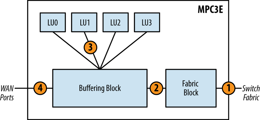
The MPC3E is the first modular line card for the MX Series to accept 100G and 40G MICs. It’s been designed from the ground up to support interfaces beyond 10GE, but also remains compatible with some legacy MICs.
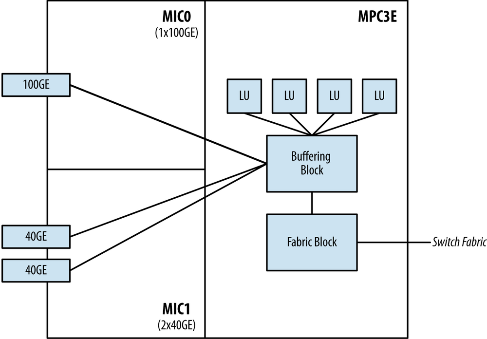
There are several new and improved features on the MPC3E. The most notable is that the Buffering Block has been increased to support 130 Gbps and number of Lookup Blocks has increased to four in order to support 100GE interfaces. The other major change is that the fabric switching functionality has been moved out of the Buffering Block and into a new Fabric Functional Block.
The MPC3E can provide line-rate performance for a single 100GE interface; otherwise it’s known that this line card is oversubscribed 1.5:1. For example, the MPC3E can support 2x100GE interfaces, but the Buffering Block can only handle 130Gbps. This can be written as 200:130, or roughly 1.5:1 oversubscription.
Enhanced Queuing isn’t supported on the MPC3E due to the lack of a Dense Queuing Block. However, this doesn’t mean that the MPC3E isn’t capable of class of service. The Buffering Block, just like the MPC-3D-16x10GE-SFPP, is capable of basic port-level class of service.
All MPC line cards previous to the MPC3E had a single Lookup Block per Trio chipset; thus, no Lookup Block synchronization was required. The MPC3E is the first MPC to introduce multiple Lookup Blocks. This creates an interesting challenge in synchronizing the Lookup Block operations.
In general, the Buffering Block will spray packets across all Lookup Blocks in a round-robin fashion. This means that a particular traffic flow will be processed by multiple Lookup Blocks.
At a high level, the MPC3E learns the source MAC address from the WAN ports. One of the four Lookup Blocks is designated as the master and the three remaining Lookup blocks are designated as the slaves.
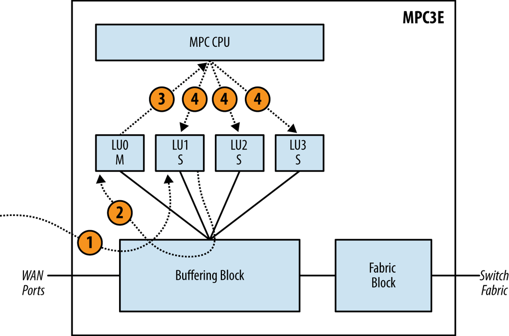
The Master Lookup Block is responsible for updating the other Slave Lookup Blocks. Figure 1-26 illustrates the steps taken to synchronize all of the Lookup Blocks.
The packet enters the Buffering Block and happens to be sprayed to LU1, which is designated as a Slave Lookup Block.
LU1 updates its own table with the source MAC address. It then notifies the Master Lookup Block LU0. The update happens via the Buffering Block to reach LU0.
The Master Lookup Block LU0 receives the source MAC address update and updates its local table accordingly. LU0 sends the source MAC address update to the MPC CPU.
The MPC CPU receives the source MAC address update and in turn updates all Lookup Blocks in parallel.
The MPC3E learns destination MAC addresses based off the packet received from other PFEs over the switch fabric. Unlike the source MAC learning, there’s no concept of a master or slave Lookup Block.
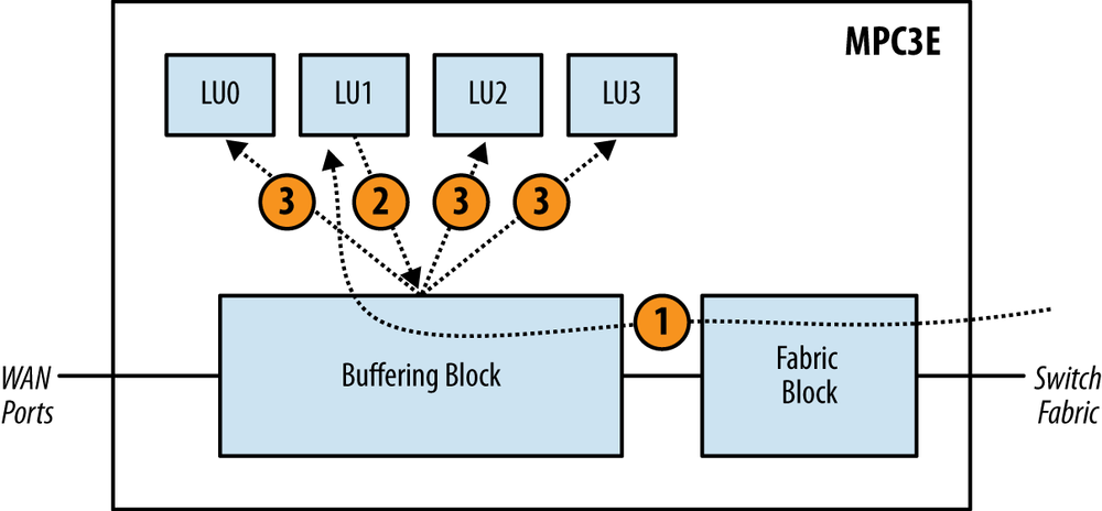
The Lookup Block that receives the packet from the switch fabric is responsible for updating the other Lookup Blocks. Figure 1-27 illustrates how destination MAC addresses are synchronized:
The packet enters the Fabric Block and Buffering Block. The packet happens to be sprayed to LU1. LU1 updates its local table.
LU1 then sends updates to all other Lookup Blocks via the Buffering Block.
The Buffering Block takes the update from LU1 and then updates the other Lookup Blocks in parallel. As each Lookup Block receives the update, the local table is updated accordingly.
Recall that the Buffering Block on the MPC3E sprays packets across Lookup Blocks evenly, even for the same traffic flow. Statistically, each Lookup Block receives about 25% of all traffic. When defining and configuring a policer, the MPC3E must take the bandwidth and evenly distribute it among the Lookup Blocks. Thus each Lookup Block is programmed to police 25% of the configured policer rate. Let’s take a closer look:
firewall {
    policer 100M {
        if-exceeding {
            bandwidth-limit 100m;
            burst-size-limit 6250000;
        }
        then discard;
    }
}
The example policer 100M is
configured to enforce a bandwidth-limit of 100m. In the case of the MPC3E, each
Lookup Block will be configured to police 25m. Because packets are statistically
distributed round-robin to all four Lookup blocks evenly, the
aggregate will equal the original policer bandwidth-limit of 100m. 25m * 4 (Lookup Blocks) = 100m.
Now that you have an understanding of the different Trio functional blocks and the layout of each line card, let’s take a look at how a packet is processed through each of the major line cards. Because there are so many different variations of functional blocks and line cards, let’s take a look at the most sophisticated configurations that use all available features.
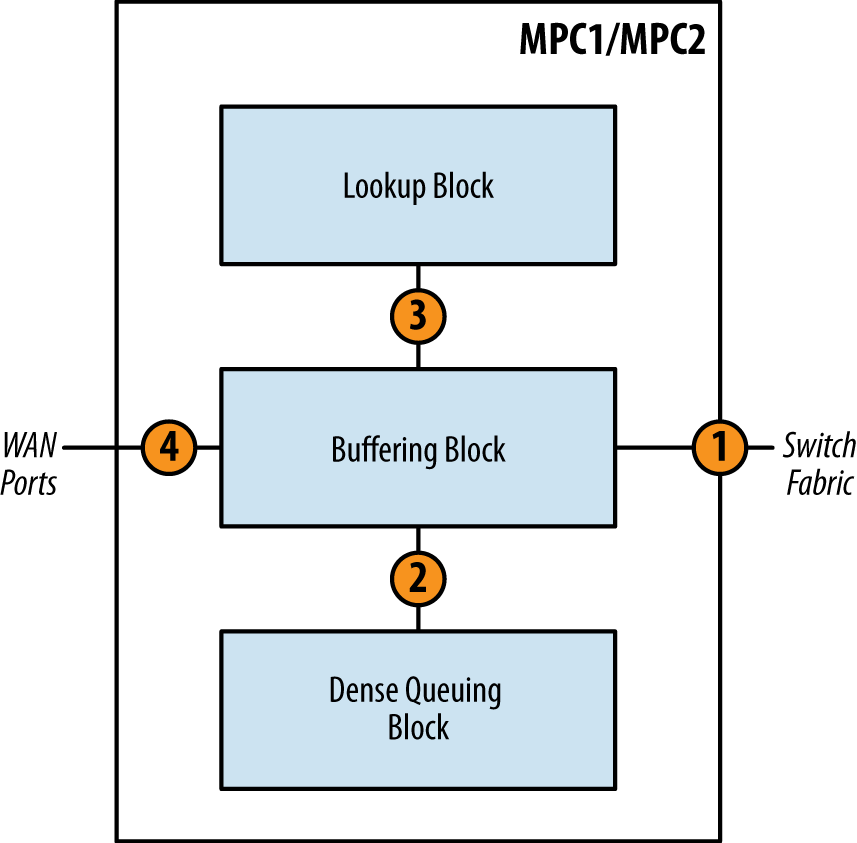
The only difference between the MPC1 and MPC2 at a high level is the number of Trio chipsets. Otherwise, they are operationally equivalent. Let’s take a look at how a packet moves through the Trio chipset. There are couple of scenarios: ingress and egress.
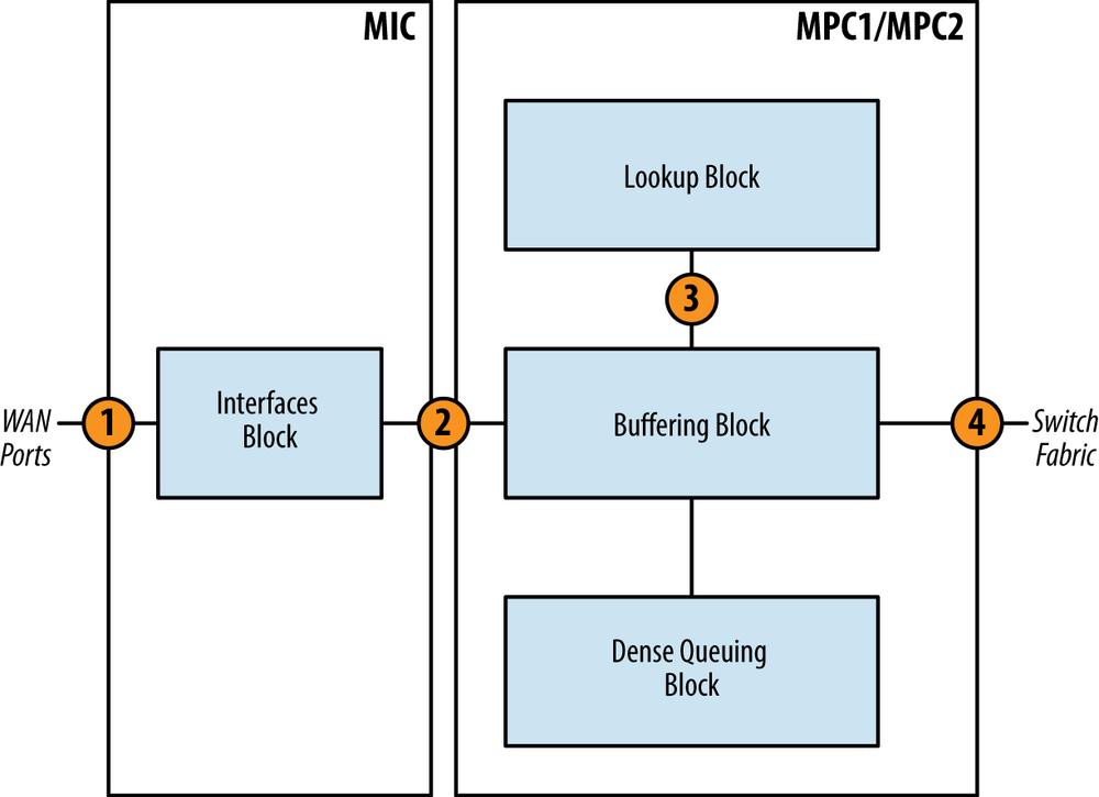
Ingress packets are received from the WAN ports on the MIC and are destined to another PFE.
The packet enters the Interfaces Block from the WAN ports. The Interfaces Block will inspect each packet and perform preclassification. Depending on the type of packet, it will be marked as high or low priority.
The packet enters the Buffering Block. The Buffering Block will enqueue the packet as determined by the preclassification and service the high priority queue first.
The packet enters the Lookup Block. A route lookup is performed and any services such as firewall filters, policing, statistics, and QoS classification are performed.
The packet is sent back to the Buffering Block and is enqueued into the switch fabric where it will be destined to another PFE. If the packet is destined to a WAN port within itself, it will simply be enqueued back to the Interfaces Block.
Egress packets are handled a bit differently. The major difference is that the Dense Queuing Block will perform class of service, if configured, on egress packets.
The packet enters the Buffering Block. If class of service is configured, the Buffering Block will send the packet to the Dense Queuing Block.
The packet enters the Dense Queuing Block. The packet will then be subject to scheduling, shaping, and any other hierarchical class of service as required. Packets will be enqueued as determined by the class of service configuration. The Dense Queuing Block will then dequeue packets that are ready for transmission and send them to the Buffering Block.
The Buffering Block receives the packet and sends it to the Lookup Block. A route lookup is performed as well as any services such as firewall filters, policing, statistics, and accounting.
The packet is then sent out to the WAN interfaces for transmission.
The packet flow of the MPC3E is similar to the MPC1 and MPC2, with a couple of notable differences: introduction of the Fabric Block and multiple Lookup Blocks. Let’s review the ingress packet first:
The packet enters the Buffering Block from the WAN ports and is subject to preclassification. Depending on the type of packet, it will be marked as high or low priority. The Buffering Block will enqueue the packet as determined by the preclassification at service the high-priority queue first. A Lookup Block is selected via round-robin and the packet is sent to that particular Lookup Block.
The packet enters the Lookup Block. A route lookup is performed and any services such as firewall filters, policing, statistics, and QoS classification are performed. The Lookup Block sends the packet back to the Buffering Block.
The packet is sent back to the Fabric Block and is enqueued into the switch fabric where it will be destined to another PFE. If the packet is destined to a WAN port within itself, it will simply be enqueued back to the Interfaces Block.

Egress packets are very similar to ingress, but the direction is simply reversed. The only major difference is that the Buffering Block will perform basic class of service, as it doesn’t support enhanced queuing due to the lack of a Dense Queuing Block.
The packet is received from the switch fabric and sent to the Fabric Block. The Fabric Block sends the packet to the Buffering Block.
The packet enters the Buffering Block. The packet will then be subject to scheduling, shaping, and any other class os service as required. Packets will be enqueued as determined by the class of service configuration. The Buffering Block will then dequeue packets that are ready for transmission and send them to a Lookup Block selected via round-robin.
The packet enters the Lookup Block. A route lookup is performed as well as any services such as firewall filters, policing, statistics, and QoS classification. The Lookup Block sends the packet back to the Buffering Block.
The Buffering Block receives the packet and sends it to the WAN ports for transmission.
As described previously, the MICs provide the physical ports and are modules that are to be installed into various MPCs. Two MICs can be installed into any of the MPCs. There is a wide variety of physical port configurations available. The speeds range from 1G to 100G and support different media such as copper or optical.
- MIC-3D-20GE-SFP
Supports 20x1G SFP ports
- MIC-3D-40GE-TX
Double-wide MIC that supports 40x1G RJ-45
- MIC-3D-2XGE-XFP
Supports 2x10G XFP ports
- MIC-3D-4XGE-XFP
Supports 4x10G XFP ports; only operates in UPOH mode
- MIC-3D-1X100G-CFP
Supports 1x100G CFP port
- MIC-3D-4CHOC3-2CHOC12
Supports four ports of channelized OC-3 or two ports of channelized OC-12
- MIC-3D-4OC4OC12-1OC48
Supports four ports of nonchannelized OC-3 or OC-12 or one port of nonchannelized OC-48
- MIC-3D-8CHOC3-4CHOC12
Supports eight ports of channelized OC-3 or four ports of channelized OC-12
- MIC-3D-8OC3OC12-4OC48
Supports eight ports of nonchannelized OC-3 through OC-12 or four ports of nonchannelized OC-48
- MIC-3D-8CHDS3-E3-B
Supports eight ports of channelized DS3 or non-channelized E3
- MIC-3D-8DS3-E3
Supports eight ports of nonchannelized DS3 or nonchannelized E3
Note
The MIC-3D-40GE-TX is a bit of an odd man out as it’s a double-wide MIC that consumes both MIC slots on the MPC.
Being modular in nature, the MICs are able to be moved from one MPC to another. They are hot-swappable and do not require a reboot to take effect. MICs offer the greatest investment protection as they’re able to be used across all of the MX platforms and various MPCs. However, there are a few caveats specific to the 4x10GE and 1x100GE MICs. Please see the following compatibility table to determine what MIC can be used where.
Table 1-9. MIC compatibility chart
MIC | MPC1 | MPC2 | MPC3 | MX80 | MX240 | MX480 | MX960 |
|---|---|---|---|---|---|---|---|
MIC-3D-20GE-SFP | Yes | Yes | Yes | Yes | Yes | Yes | Yes |
MIC-3D-40GE-TX | Yes | Yes | No | Yes | Yes | Yes | Yes |
MIC-3D-2XGE-XFP | Yes | Yes | Yes | Yes | Yes | Yes | Yes |
MIC-3D-4XGE-XFP | No | Yes | No | No | Yes | Yes | Yes |
MIC-3D-1X100G-CFP | No | No | Yes | No | Yes | Yes | Yes |
MIC-3D-4CHOC3-2CHOC12 | Yes | Yes | No | Yes | Yes | Yes | Yes |
MIC-3D-4OC3OC12-1OC48 | Yes | Yes | No | Yes | Yes | Yes | Yes |
MIC-3D-8CHOC3-4CHOC12 | Yes | Yes | No | Yes | Yes | Yes | Yes |
MIC-3D-8OC3OC12-4OC48 | Yes | Yes | No | Yes | Yes | Yes | Yes |
MIC-3D-8CHDS3-E3-B | Yes | Yes | No | Yes | Yes | Yes | Yes |
MIC-3D-8DS3-E3 | Yes | Yes | No | Yes | Yes | Yes | Yes |
The MX240, MX480, and MX960 are able to operate with different types of line cards at the same time. For example, it’s possible to have a MX240 operate with FPC1 using a DPCE-R line card while FPC2 using a MX-MPC-R-B line card. Because there are many different variations of DPC, MPC, Ethernet, and routing options, a chassis control feature called network services can be used force the chassis into a particular compatibility mode.
If the network services aren’t configured, then by default when a MX chassis boots up, the FPC that is powered up first will determine the mode of the chassis. If the first FPC to be powered up is DPC, then only DPCs within the chassis will be allowed to power up. Alternatively, if the first powered up FPC is MPC, then only MPCs within the chassis will be allowed to power up.
The chassis network services can be configured with set chassis network-services knob. There are
five different options the network services can be set to:
ipAllow all line cards to power up, except for DPCE-X. The
iphints toward being able to route, thus line cards such as the DPCE-X will not be allowed to power up as they only support bridging.ethernetAllow all line cards to power up. This includes the DPCE-X, DPCE-R, and DPCE-Q.
enhanced-ipAllow all Trio-based MPCs to be powered up.
enhanced-ethernetAllow only Trio-based MPC-3D, MPC-3D-Q, and MPC-3D-EQ line cards to be powered up.
all-ipAllow both DPC and MPC line cards to be powered up, except for DPCE-X line cards. This option was hidden in Junos 10.0 and was used for manufacturing testing.
all-ethernetAllow both DPC and MPC line cards to be powered up. This includes the DPCE-X and other line cards that are Layer 2 only. This option was hidden in Junos 10.0 and was used for manufacturing testing.
Warning
The all-ip and all-ethernet modes are deprecated and
shouldn’t be used. These options were used exclusively for developer
and manufacturing testing.
It’s possible to change the value of network services while the chassis is running.
There are many different combinations; some require a reboot, while
others do not:
- Change from
iptoethernet Any DPCE-X will boot up. No reboot required.
- Change from
ethernettoip This change will generate a commit error. It’s required that any DPCE-X line cards be powered off before the change can take effect.
- Change
enhanced-iptoenhanced-ethernet Any MPC-3D, MPC-3D-Q, and MPC-3D-EQ line cards will boot up. No reboot required.
- Change
enhanced-ethernettoenhanced-ip No change.
- Change between
iporethernettoenhanced-iporenhanced-ethernet The commit will complete but will require a reboot of the chassis.
To view which mode the network services is currently set to, use
the show chassis network-services
command:
dhanks@R1> show chassis network-services
Network Services Mode: IP

dhanks@R1>
Get Juniper MX Series now with the O’Reilly learning platform.
O’Reilly members experience books, live events, courses curated by job role, and more from O’Reilly and nearly 200 top publishers.

