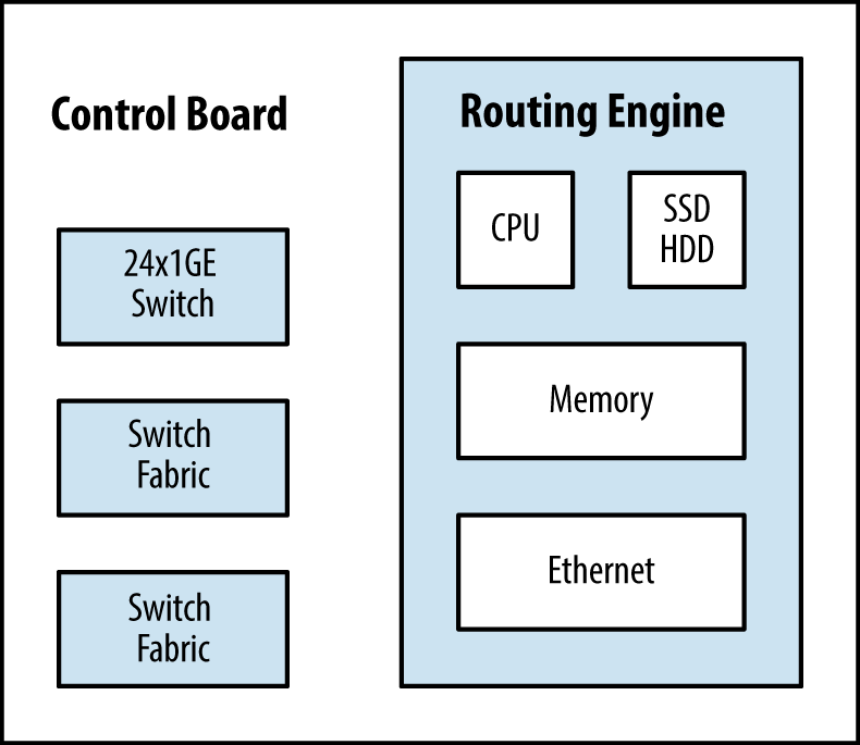
At the heart of the MX Series is the Switch and Control Board (SCB). It’s the glue that brings everything together. The SCB has three primary functions: switch data between the line cards, control the chassis, and house the routing engine. The SCB is a single-slot card and has a carrier for the routing engine on the front. A SCB contains the following components:
An Ethernet switch for chassis management
Two switch fabrics
Control board (CB) and routing engine state machine for mastership arbitration
Routing engine carrier
Depending on the chassis and level of redundancy, the number of SCBs vary. The MX240 and MX480 require two SCBs for 1 + 1 redundancy, whereas the MX960 requires three SCBs for 2 + 1 redundancy.
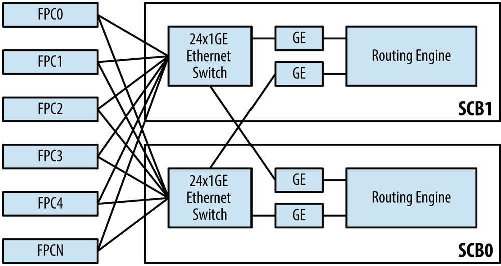
Each SCB contains a 24-port Gigabit Ethernet switch. This internal switch connects the two routing engines and all of the FPCs together. Each routing engine has two networking cards. The first NIC is connected to the local onboard Ethernet switch, whereas the second NIC is connected to the onboard Ethernet switch on the other SCB. This allows the two routing engines to have internal communication for features such as NSR, NSB, ISSU, and administrative functions such as copying files between the routing engines.
Each Ethernet switch has connectivity to each of the FPCs. This allows for the routing engines to communicate to the Junos microkernel onboard each of the FPCs. A good example would be when a packet needs to be processed by the routing engine. The FPC would need to send the packet across the SCB Ethernet switch and up to the master routing engine. Another good example is when the routing engine modifies the forwarding information base (FIB) and updates all of the PFEs with the new information.
It’s possible to view information about the Ethernet switch inside
of the SCB. The command show chassis
ethernet-switch will show which ports on the Ethernet switch
are connected to which devices at a high level.
{master}
dhanks@R1-RE0> show chassis ethernet-switch

Displaying summary for switch 0
Link is good on GE port 1 connected to device: FPC1
  Speed is 1000Mb
  Duplex is full
  Autonegotiate is Enabled
  Flow Control TX is Disabled
  Flow Control RX is Disabled

Link is good on GE port 2 connected to device: FPC2
  Speed is 1000Mb
  Duplex is full
  Autonegotiate is Enabled
  Flow Control TX is Disabled
  Flow Control RX is Disabled

Link is good on GE port 12 connected to device: Other RE
  Speed is 1000Mb
  Duplex is full
  Autonegotiate is Enabled
  Flow Control TX is Disabled
  Flow Control RX is Disabled

Link is good on GE port 13 connected to device: RE-GigE
  Speed is 1000Mb
  Duplex is full
  Autonegotiate is Enabled
  Flow Control TX is Disabled
  Flow Control RX is Disabled
  Receive error count = 012032
The Ethernet switch will only be connected to FPCs that are online and routing engines. As you can see, R1-RE0 is showing that its Ethernet switch is connected to both FPC1 and FPC2. Let’s check the hardware inventory to make sure that this information is correct.
{master}
dhanks@R1-RE0> show chassis fpc
                     Temp  CPU Utilization (%)   Memory    Utilization (%)
Slot State            (C)  Total  Interrupt      DRAM (MB) Heap     Buffer
  0  Empty
  1  Online            35     21          0       2048       12         13
  2  Online            34     22          0       2048       11         16

{master}
dhanks@R1-RE0>
As you can see, FPC1 and FPC2 are both online. This matches the
previous output from the show chassis
ethernet-switch. Perhaps the astute reader noticed that the
Ethernet switch port number is paired with the FPC location. For
example, GE port 1 is connected to FPC1 and GE port 2 is connected to
FPC2, so on and so forth all the way up to FPC11.
Although each Ethernet switch has 24 ports, only 14 are being used. GE ports 0 through 11 are reserved for FPCs, while GE ports 12 and 13 are reserved for connections to the routing engines.
Table 1-10. MX-SCB Ethernet switch port assignments
GE Port | Description |
|---|---|
0 | FPC0 |
1 | FPC1 |
2 | FPC2 |
3 | FPC3 |
4 | FPC4 |
5 | FPC5 |
6 | FPC6 |
7 | FPC7 |
8 | FPC8 |
9 | FPC9 |
10 | FPC10 |
11 | FPC11 |
12 | Other Routing Engine |
13 | Routing Engine GE |
Note
One interesting note is that the show
chassis ethernet-switch command is relative to where it’s
executed. GE port 12 will always be the other routing engine. For
example, when the command is executed from re0, the GE port 12 would
be connected to re1 and GE port 13 would be connected to re0.
To view more detailed information about a particular GE port on
the SCB Ethernet switch, you can use the command show chassis ethernet-switch statistics
command. Let’s take a closer look at GE port 13, which is connected to
the local routing engine.
{master}
dhanks@R1-RE0> show chassis ethernet-switch statistics 13

Displaying port statistics for switch 0
Statistics for port 13 connected to device RE-GigE:
  TX Packets 64 Octets        29023890
  TX Packets 65-127 Octets    101202929
  TX Packets 128-255 Octets   14534399
  TX Packets 256-511 Octets   239283
  TX Packets 512-1023 Octets  610582
  TX Packets 1024-1518 Octets  1191196
  TX Packets 1519-2047 Octets  0
  TX Packets 2048-4095 Octets  0
  TX Packets 4096-9216 Octets  0
  TX 1519-1522 Good Vlan frms  0
  TX Octets                   146802279
  TX Multicast Packets        4
  TX Broadcast Packets        7676958
  TX Single Collision frames  0
  TX Mult. Collision frames   0
  TX Late Collisions          0
  TX Excessive Collisions     0
  TX Collision frames         0
  TX PAUSEMAC Ctrl Frames     0
  TX MAC ctrl frames          0
  TX Frame deferred Xmns      0
  TX Frame excessive deferl   0
  TX Oversize Packets         0
  TX Jabbers                  0
  TX FCS Error Counter        0
  TX Fragment Counter         0
  TX Byte Counter             2858539809

<output truncated for brevity>
Although the majority of the traffic is communication between the two routing engines, exception traffic is also passed through the Ethernet switch. When an ingress PFE receives a packet that needs additional processing—such as a BGP update or SSH traffic destined to the router—the packet needs to be encapsulated and sent to the routing engine. The same is true if the routing engine is sourcing traffic that needs to be sent out an egress PFE.
The switch fabric connects all of the ingress and egress PFEs within the chassis to create a full mesh. Each SCB has two switch fabrics. Depending on the MX chassis, each switch fabric can have either one or two fabric planes.
The MX240 and MX480 support two SCBs for a total of four switch fabrics and eight fabric planes. The MX960 supports three SCBs for a total of six switch fabrics and six fabric planes.
This begs the question, what is a fabric plane? Think of the switch fabric as a fixed unit that can support N connections. When supporting 48 PFEs on the MX960, all of these connections on the switch fabric are completely consumed. Now think about what happens when you apply the same logic to the MX480. Each switch fabric now only has to support 24 PFEs, thus half of the connections aren’t being used. What happens on the MX240 and MX480 is that these unused connections are grouped together and another plane is created so that the unused connections can now be used. The benefit is that the MX240 and MX480 only require a single SCB to provide line rate throughput, thus only require an additional SCB for 1 + 1 SCB redundancy.
Table 1-11. MX-SCB fabric plane scale and redundancy assuming four PFEs per FPC
MX-SCB | MX240 | MX480 | MX960 |
|---|---|---|---|
PFEs | 12 | 24 | 48 |
SCBs | 2 | 2 | 3 |
Switch Fabrics | 4 | 4 | 6 |
Fabric Planes | 8 | 8 | 6 |
Spare Planes | 4 (1 + 1 SCB redundancy) | 4 (1 + 1 SCB redundancy) | 2 (2 + 1 SCB redundancy) |
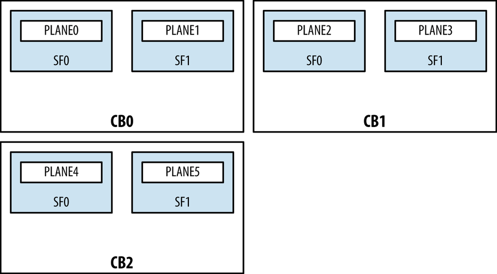
Given that the MX240 and MX480 only have to support a fraction of the number of PFEs as the MX960, we’re able to group together the unused connections on the switch fabric and create a second fabric plane per switch fabric. Thus we’re able to have two fabric planes per switch fabric, as shown in Figure 1-34.
As you can see, each control board has two switch fabrics: SF0
and SF1. Each switch fabric has two fabric planes. Thus the MX240 and
MX480 have eight available fabric planes. This can be verified with
the command show chassis fabric
plane-location.
{master}
dhanks@R1-RE0> show chassis fabric plane-location
------------Fabric Plane Locations-------------
Plane 0 Control Board 0
Plane 1 Control Board 0
Plane 2 Control Board 0
Plane 3 Control Board 0
Plane 4 Control Board 1
Plane 5 Control Board 1
Plane 6 Control Board 1
Plane 7 Control Board 1
{master}
dhanks@R1-RE0>Because the MX240 and MX480 only support two SCBs, they support
1 + 1 SCB redundancy. By default, SCB0 is in the
Online state and processes all of the forwarding.
SCB1 is in the Spare state and waits to take over
in the event of a SCB failure. This can be illustrated with the
command show chassis fabric
summary.
{master}
dhanks@R1-RE0> show chassis fabric summary
Plane State Uptime
0 Online 18 hours, 24 minutes, 57 seconds
1 Online 18 hours, 24 minutes, 52 seconds
2 Online 18 hours, 24 minutes, 51 seconds
3 Online 18 hours, 24 minutes, 46 seconds
4 Spare 18 hours, 24 minutes, 46 seconds
5 Spare 18 hours, 24 minutes, 41 seconds
6 Spare 18 hours, 24 minutes, 41 seconds
7 Spare 18 hours, 24 minutes, 36 seconds
{master}
dhanks@R1-RE0>As expected, planes 0 to 3 are Online and planes 4 to 7 are Spare. Another useful tool from this command
is the Uptime. The Uptime
column displays how long the SCB has been up since the last boot.
Typically, each SCB will have the same uptime as the system itself,
but it’s possible to hot-swap SCBs during a maintenance; the new SCB
would then show a smaller uptime than the others.
The MX960 is a different beast because of the PFE scale involved. It has to support twice the number of PFEs as the MX480, while maintaining the same line rate performance requirements. An additional SCB is mandatory to support these new scaling and performance requirements.
Unlike the MX240 and MX480, the switch fabrics only support a
single fabric plane because all available links are required to create
a full mesh between all 48 PFEs. Let’s verify this with the command
show chassis fabric
        plane-location
.
{master}
dhanks@MX960> show chassis fabric plane-location
------------Fabric Plane Locations-------------
Plane 0                         Control Board 0
Plane 1                         Control Board 0
Plane 2                         Control Board 1
Plane 3                         Control Board 1
Plane 4                         Control Board 2
Plane 5                         Control Board 2

{master}
dhanks@MX960>
As expected, things seem to line up nicely. We see there are two
switch fabrics per control board. The MX960 supports up to three SCBs
providing 2 + 1 SCB redundancy. At least two SCBs are required for
basic line rate forwarding, and the third SCB provides redundancy in
case of a SCB failure. Let’s take a look at the command show chassis fabric summary.
{master}
dhanks@MX960> show chassis fabric summary
Plane   State    Uptime
 0      Online   18 hours, 24 minutes, 22 seconds
 1      Online   18 hours, 24 minutes, 17 seconds
 2      Online   18 hours, 24 minutes, 12 seconds
 3      Online   18 hours, 24 minutes, 6 seconds
 4      Spare    18 hours, 24 minutes, 1 second
 5      Spare    18 hours, 23 minutes, 56 seconds

{master}
dhanks@MX960>
Everything looks good. SCB0 and SCB1 are
Online, whereas the redundant SCB2 is standing by
in the Spare state. If SCB0 or SCB1
fails, SCB2 will immediately transition to the Online state and allow the router to keep
forwarding traffic at line rate.
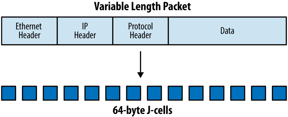
As packets move through the MX from one PFE to another, they need to traverse the switch fabric. Before the packet can be placed onto the switch fabric, it first must be broken into J-cells. A J-cell is a 64-byte fixed-width unit.
The benefit of J-cells is that it’s much easier for the router to process, buffer, and transmit fixed-width data. When dealing with variable length packets with different types of headers, it adds inconsistency to the memory management, buffer slots, and transmission times. The only drawback when segmenting variable data into a fixed-width unit is the waste, referred to as “cell tax.” For example, if the router needed to segment a 65-byte packet, it would require two J-cells: the first J-cell would be fully utilized, the second J-cell would only carry 1 byte, and the other 63 bytes of the J-cell would go unused.
Note
For those of you old enough (or savvy enough) to remember ATM, go ahead and laugh.
There are some additional fields in the J-cell to optimize the transmission and processing:
Request source and destination address
Grant source and destination address
Cell type
Sequence number
Data (64 bytes)
Checksum
Each PFE has an address that is used to uniquely identify it within the fabric. When J-cells are transmitted across the fabric a source and destination address is required, much like the IP protocol. The sequence number and cell type aren’t used by the fabric, but instead are important only to the destination PFE. The sequence number is used by the destination PFE to reassemble packets in the correct order. The cell type identifies the cell as one of the following: first, middle, last, or single cell. This information assists in the reassembly and processing of the cell on the destination PFE.
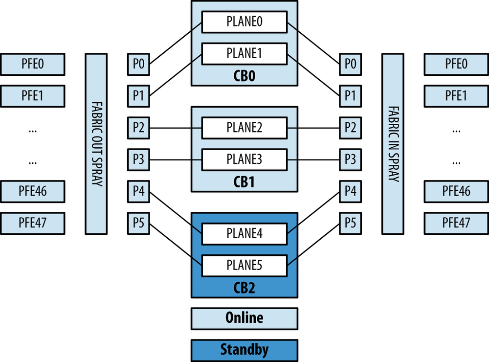
As the packet leaves the ingress PFE, the Trio chipset will segment the packet into J-cells. Each J-cell will be sprayed across all available fabric links. The following illustration represents a MX960 fully loaded with 48 PFEs and 3 SCBs. The example packet flow is from left to right.
J-cells will be sprayed across all available fabric links. Keep
in mind that only PLANE0 through
PLANE3 are Online, whereas PLANE4 and PLANE5 are Standby.
Before the J-cell can be transmitted to the destination PFE, it needs to go through a three-step request and grant process:
The source PFE will send a request to the destination PFE.
The destination PFE will respond back to the source PFE with a grant.
The source PFE will transmit the J-cell.
The request and grant process guarantees the delivery of the J-cell through the switch fabric. An added benefit of this mechanism is the ability to quickly discover broken paths within the fabric and provide a method of flow control.
As the J-cell is placed into the switch fabric, it’s placed into one of two fabric queues: high or low. In the scenario where there are multiple source PFEs trying to send data to a single destination PFE, it’s going to cause the destination PFE to be oversubscribed. One tool that’s exposed to the network operator is the fabric priority knob in the class of service configuration. When you define a forwarding class, you’re able to set the fabric priority. By setting the fabric priority to high for a specific forwarding class, it will ensure that when a destination PFE, is congested, the high-priority traffic will be delivered. This is covered more in detail in Chapter 5.
The MX SCB is the first-generation switch fabric for the MX240, MX480, and MX960. This MX SCB was designed to work with the first-generation DPC line cards. As described previously, the MX SCB provides line-rate performance with full redundancy.
The MX240 and MX480 provide 1 + 1 MX SCB redundancy when used with the DPC line cards. The MX960 provides 2 + 1 MX SCB redundancy when used with the DPC line cards.
Each of the fabric planes on the first-generation SCB is able to process 20 Gbps of bandwidth. The MX240 and MX480 use eight fabric planes across two SCBs, whereas the MX960 uses six fabric planes across three SCBs. Because of the fabric plane virtualization, the aggregate fabric bandwidth between the MX240, MX480, and MX960 is different.
Table 1-12. First-Generation SCB bandwidth
Model | SCBs | Switch Fabrics | Fabric Planes | Fabric Bandwidth per Slot |
|---|---|---|---|---|
MX240 | 2 | 4 | 8 | 160 Gbps |
MX480 | 2 | 4 | 8 | 160 Gbps |
MX960 | 3 | 6 | 6 | 120 Gbps |
The only caveat is that the first-generation MX SCBs are not able to provide line-rate redundancy with some of the new-generation MPC line cards. When the MX SCB is used with the newer MPC line cards, it places additional bandwidth requirements onto the switch fabric. The additional bandwidth requirements come at a cost of oversubscription and a loss of redundancy.
As described previously, the MX240 and MX480 have a total of eight fabric planes when using two MX SCBs. When the MX SCB and MPCs are being used on the MX240 and MX480, there’s no loss in performance and all MPCs are able to operate at line rate. The only drawback is that all fabric planes are in use and are Online.
Let’s take a look at a MX240 with the first-generation MX SCBs and new-generation MPC line cards.
{master}
dhanks@R1-RE0> show chassis hardware | match FPC
FPC 1            REV 15   750-031088   ZB7956            MPC Type 2 3D Q
FPC 2            REV 25   750-031090   YC5524            MPC Type 2 3D EQ

{master}
dhanks@R1-RE0> show chassis hardware | match SCB
CB 0             REV 03   710-021523   KH6172            MX SCB
CB 1             REV 10   710-021523   ABBM2781          MX SCB

{master}
dhanks@R1-RE0> show chassis fabric summary
Plane   State    Uptime
 0      Online   10 days, 4 hours, 47 minutes, 47 seconds
 1      Online   10 days, 4 hours, 47 minutes, 47 seconds
 2      Online   10 days, 4 hours, 47 minutes, 47 seconds
 3      Online   10 days, 4 hours, 47 minutes, 47 seconds
 4      Online   10 days, 4 hours, 47 minutes, 47 seconds
 5      Online   10 days, 4 hours, 47 minutes, 46 seconds
 6      Online   10 days, 4 hours, 47 minutes, 46 seconds
 7      Online   10 days, 4 hours, 47 minutes, 46 seconds
As we can see, R1 has the
first-generation MX SCBs and new-generation MPC2 line cards. In this
configuration, all eight fabric planes are Online
and processing J-cells.
If a MX SCB fails on a MX240 or MX480 using the new-generation MPC line cards, the router’s performance will degrade gracefully. Losing one of the two MX SCBs would result in a loss of half of the router’s performance.
In the case of the MX960, it has six fabric planes when using three MX SCBs. When the first-generation MX SCBs are used on a MX960 router, there isn’t enough fabric bandwidth to provide line-rate performance for the MPC-3D-16X10GE-SPFF or MPC3-3D line cards. However, with the MPC1 and MPC2 line cards, there’s enough fabric capacity to operate at line rate, \ except when used with the 4x10G MIC.
Let’s take a look at a MX960 with a first-generation MX SCB and second-generation MPC line cards.
dhanks@MX960>show chassis hardware | match SCBCB 0 REV 03.6 710-013385 JS9425 MX SCB CB 1 REV 02.6 710-013385 JP1731 MX SCB CB 2 REV 05 710-013385 JS9744 MX SCB dhanks@MX960>show chassis hardware | match FPCFPC 2 REV 14 750-031088 YH8454 MPC Type 2 3D Q FPC 5 REV 29 750-031090 YZ6139 MPC Type 2 3D EQ FPC 7 REV 29 750-031090 YR7174 MPC Type 2 3D EQ dhanks@MX960>show chassis fabric summaryPlane State Uptime 0 Online 11 hours, 21 minutes, 30 seconds 1 Online 11 hours, 21 minutes, 29 seconds 2 Online 11 hours, 21 minutes, 29 seconds 3 Online 11 hours, 21 minutes, 29 seconds 4 Online 11 hours, 21 minutes, 28 seconds 5 Online 11 hours, 21 minutes, 28 seconds
As you can see, the MX960 has three of the first-generation MX
SCB cards. There’s also three second-generation MPC line cards. Taking
a look at the fabric summary, we can surmise that all six fabric
planes are Online. When using
high-speed MPCs and MICs, the oversubscription is approximately 4:3
with the first-generation MX SCB. Losing a MX SCB with the
new-generation MPC line cards would cause the MX960 to gracefully
degrade performance by a third.
The second-generation Enhanced MX Switch Control Board (SCBE) doubles performance from the previous MX SCB. The SBCE was designed to be used specifically with the new-generation MPC line cards to provide full line-rate performance and redundancy without a loss of bandwidth.
Table 1-13. Second-generation SCBE bandwidth
Model | SCBs | Switch Fabrics | Fabric Planes | Fabric Bandwidth Per Slot |
|---|---|---|---|---|
MX240 | 2 | 4 | 8 | 320 Gbps |
MX480 | 2 | 4 | 8 | 320 Gbps |
MX960 | 3 | 6 | 6 | 240 Gbps |
When the SCBE is used with the MX240 and MX480, only one SCBE is required for full line-rate performance and redundancy.
Let’s take a look at a MX480 with two SCBEs and 100G MPC3 line cards.
dhanks@paisa>show chassis hardware | match SCBCB 0 REV 14 750-031391 ZK8231 Enhanced MX SCB CB 1 REV 14 750-031391 ZK8226 Enhanced MX SCB dhanks@paisa>show chassis hardware | match FPCFPC 0 REV 24 750-033205 ZJ6553 MPC Type 3 FPC 1 REV 21 750-033205 ZG5027 MPC Type 3 dhanks@paisa>show chassis fabric summaryPlane State Uptime 0 Online 5 hours, 54 minutes, 51 seconds 1 Online 5 hours, 54 minutes, 45 seconds 2 Online 5 hours, 54 minutes, 45 seconds 3 Online 5 hours, 54 minutes, 40 seconds 4 Spare 5 hours, 54 minutes, 40 seconds 5 Spare 5 hours, 54 minutes, 35 seconds 6 Spare 5 hours, 54 minutes, 35 seconds 7 Spare 5 hours, 54 minutes, 30 seconds
Much better. You can see that there are two SCBEs as well 100G
MPC3 line cards. When taking a look at the fabric summary, we see that
all eight fabric planes are present. The big difference is that now
four of the planes are Online while
the other four are Spare. These new
SCBEs are providing line-rate fabric performance as well as 1 + 1 SCB
redundancy.
Because the MX SCBE is twice the performance of the previous MX SCB, the MX960 can now go back to the original 2 + 1 SCB for full line-rate performance and redundancy.
Let’s check out a MX960 using three MX SCBEs and 100G MPC3 line cards.
dhanks@bellingham>show chassis hardware | match SCBCB 0 REV 10 750-031391 ZB9999 Enhanced MX SCB CB 1 REV 10 750-031391 ZC0007 Enhanced MX SCB CB 2 REV 10 750-031391 ZC0001 Enhanced MX SCB dhanks@bellingham>show chassis hardware | match FPCFPC 0 REV 14.3.09 750-033205 YY8443 MPC Type 3 FPC 3 REV 12.3.09 750-033205 YR9438 MPC Type 3 FPC 4 REV 27 750-033205 ZL5997 MPC Type 3 FPC 5 REV 27 750-033205 ZL5968 MPC Type 3 FPC 11 REV 12.2.09 750-033205 YW7060 MPC Type 3 dhanks@bellingham>show chassis fabric summaryPlane State Uptime 0 Online 6 hours, 7 minutes, 6 seconds 1 Online 6 hours, 6 minutes, 57 seconds 2 Online 6 hours, 6 minutes, 52 seconds 3 Online 6 hours, 6 minutes, 46 seconds 4 Spare 6 hours, 6 minutes, 41 seconds 5 Spare 6 hours, 6 minutes, 36 seconds
What a beautiful sight. We have three MX SCBEs in addition to
five 100G MPC3 line cards. As discussed previously, the MX960 has six
fabric planes. We can see that four of the fabric planes are Online, whereas the other two are Spare. We now have line-rate fabric
performance plus 2 + 1 MX SCBE redundancy.
Get Juniper MX Series now with the O’Reilly learning platform.
O’Reilly members experience books, live events, courses curated by job role, and more from O’Reilly and nearly 200 top publishers.
