CoS Lab
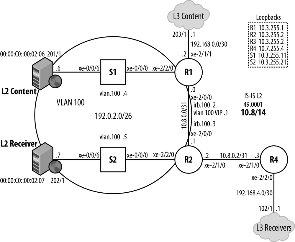
OK, after all that talk it’s time to get down to CoS business. In this section, you enable your Trio-based MX network for L2 and L3 CoS, and then verify that all has gone to plan. Figure 5-28 shows the CoS test topology.

Figure 5-28. The Trio CoS Test Topology.
The test topology does not use AE interfaces given that H-CoS support for IFL-Sets on AE is not present in 11.4R1. A single 10 Gbps link is used between the switches and routers. R1 and R2 both serve a Layer 2 domain with VLAN 100 the area of focus. The VLAN is assigned logical IP subnet (LIS) 192.0.2.0/25. R1’s irb.100 interface is assigned 192.0.2.2, while R2 is given 192.0.2.3. The VRRP VIP, owned by R1 when operational, is 192.0.2.1.
The redundant links in the L2 domain have been eliminated to constrain traffic to the single path between the L2 source and receiver to help keep the focus on CoS. IS-IS level 2 is enabled on the core backbone links between R1, R2, and R4. Passive mode is configured on the Layer 3 source and receiver ports to ensure reachability to the associated 192.168.x.x/30 subnetworks.
The initial goal is to configure and verify IP CoS is working for both L2 switched and L3 routed traffic, with the focus on R1’s configuration and operation.
Configure Unidirectional CoS
Virtually all IP networks are duplex in nature, which is to say traffic is both sent and received. A CoS design tends to be symmetric ...
Get Juniper MX Series now with the O’Reilly learning platform.
O’Reilly members experience books, live events, courses curated by job role, and more from O’Reilly and nearly 200 top publishers.

