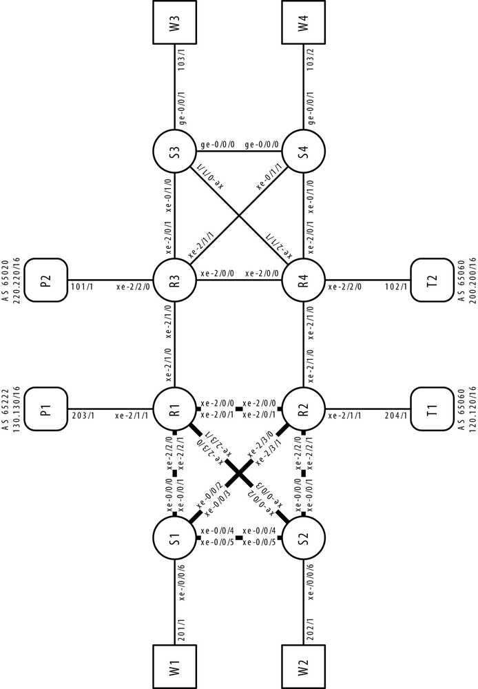
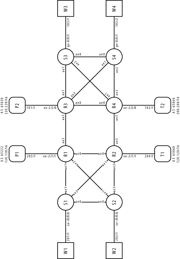
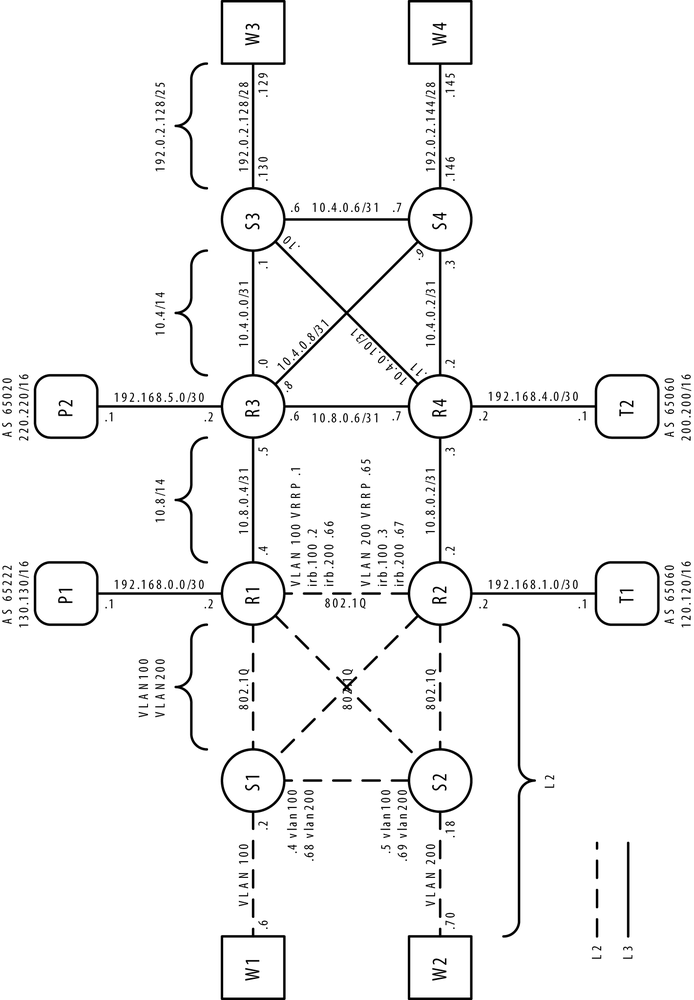
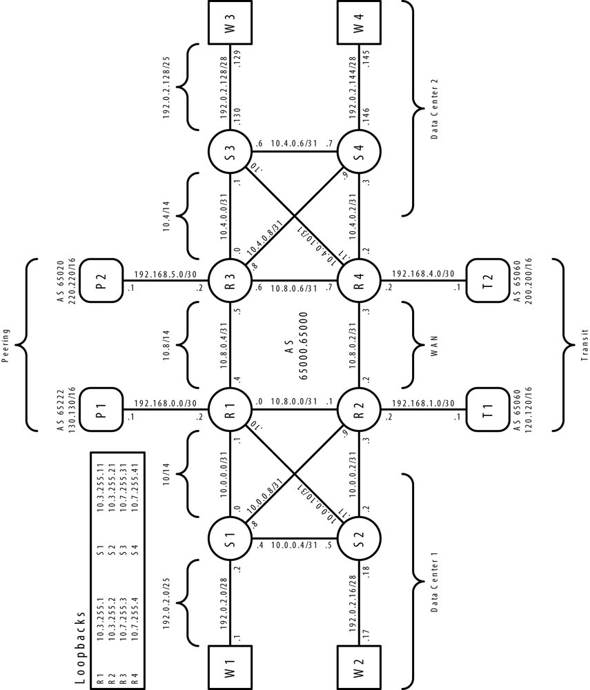
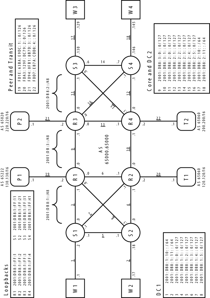
Using the same methodology found in the JNCIP-M and JNCIE-M Study Guides, this book will use a master topology and each chapter will use a subset of the devices that are needed to illustrate features and case studies. The master topology is quite extensive and includes four Juniper MX240s, two EX4500s, two EX4200s, and various port testers which can generate traffic and emulate peering and transit links. The topology is broken into three major pieces:
- Data Center 1
The left side of the topology represents Data Center 1. The devices include W1, W2, S1, S2, R1, R2, P1, and T2. The address space can be summarized as 10.0.0.0/14.
- Data Center 2
The right side of the topology represents Data Center 2. It’s common for networks to have more than one data center, so it made sense to create a master topology that closely resembles a real production network. The devices include W3, W4, S3, S4, R3, R4, P2, and T2.
- The Core
The core is really just a subset of the two data centers combined. Typically when interconnecting data centers a full mesh of WAN links aren’t cost effective, so we decided to only use a pair of links between Data Center 1 and Data Center 2.
For the sake of clarity and readability, the master topology has been broken into five figures, Figure 1 through Figure 5: Interface Names, Aggregate Ethernet Assignments, Layer 2, IPv4 Addressing, and IPv6 Addressing. The breakdown and configuration of the equipment is as follows:
| W1: Web Server 1. This is a tester port that’s able to generate traffic. |
| W2: Web Server 2. This is a tester port that’s able to generate traffic. |
| S1: Access Switch 1. This is a Juniper EX4500 providing both Layer 2 and Layer 3 access. |
| S2: Access Switch 2. This is a Juniper EX4500 providing both Layer 2 and Layer 3 access. |
| R1: Core Router/WAN Router 1. Juniper MX240 with a MPC2 Enhanced Queuing line card. |
| R2: Core Router/WAN Router 2. Juniper MX240 with a MPC2 Enhanced Queuing line card. |
| R3: Core Router/WAN Router 3. Juniper MX240 with a MPC2 line card. |
| R4: Core Router/WAN Router 4. Juniper MX240 with a MPC2 Queuing line card. |
| S3: Access Switch 3. Juniper EX4200 providing both Layer 2 and Layer 3 access. |
| S4: Access Switch 4. Juniper EX4200 providing both Layer 2 and Layer 3 access. |
| W3: Web Server 3. This is a tester port that’s able to generate traffic. |
| W4: Web Server 4. This is a tester port that’s able to generate traffic. |
| P1: Peering Router 1. This is a tester port that’s able to generate traffic. |
| P2: Peering Router 2. This is a tester port that’s able to generate traffic. |
| T1: Transit Router 1. This is a tester port that’s able to generate traffic. |
| T2: Transit Router 2. This is a tester port that’s able to generate traffic. |
Get Juniper MX Series now with the O’Reilly learning platform.
O’Reilly members experience books, live events, courses curated by job role, and more from O’Reilly and nearly 200 top publishers.
