Transient interfaces are any interfaces that the user can remove, move, or replace. These include ports on the removable cards (PICs, PIMs, IOCs, etc.). Examples of transient interfaces are Fast Ethernet, gigabit Ethernet, Asynchronous Transfer Mode (ATM), SONET, and T1/E1, as well as service PICs such as tunnels, multilinks, link services, Adaptive Services PICs (ASPs), and passive monitoring.
All Junos interfaces follow the same naming convention—the interface name followed by three numbers that indicate the location of the actual interface. The general convention is illustrated by the interface sequence MM-F/P/T, where:
- MM
Media type
- F
Chassis slot number
- P
PIC slot number
- T
Port number
The first part of the interface name is the interface media name (MM), indicating the type of interface. Common interface media names include:
aeAggregated Ethernet, a logical linkage of multiple Ethernet interfaces defined in the IEEE 802.3ad standard.
atATM, which sends fixed 53-byte cells over the transport media. This interface could also be used for ATM over digital subscriber line (DSL) connections.
brPhysical Integrated Services Digital Network (ISDN) interface.
e1Standard digital communication standard over copper at a rate of 2.048 Mbps, used mostly in Europe.
e3Standard digital communication standard over copper at a rate of 34.368 Mbps, used mostly in Europe.
t1Basic physical layer standard used by the digital signal level 1 at a rate of 1.544 Mbps, used extensively in North America.
t3Basic physical layer standard used by the digital signal level 3 at a rate of 44.736 Mbps, used extensively in North America.
fe100 Mbps standard initially created by Xerox in the 1970s for connecting multiple computers together; referred to as a LAN today.
geHigher-speed Ethernet standard at 1 Gbps.
xeHigher-speed Ethernet standard at 10 Gbps.
seInterface used for serial communications (one bit at a time). Serial interfaces include standards such as EIA 530, V.35, and X.21.
ct1T1 interface that is channelized by splitting the interface into 24 DSO channels.
The next part of the interface name is F, a chassis slot number represented by a Flexible PIC Concentrator (FPC) slot number on an M-series router, a PIM slot number on a J-series router, the IOC slot number on an SRX, or the DPC slot number on an MX.
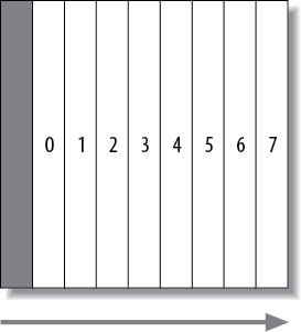
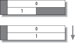
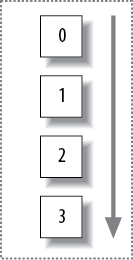
The M-series routers have two possible FPC alignments: horizontal slots or vertical slots. The larger M-series routers (M40e, M320) have vertically mounted FPCs with slot numbers starting at slot 0 and counting from left to right (see Figure 4-1). The smaller M-series routers (M7i, M10i) have horizontal slots starting at slot 0 and counting from top to bottom (see Figure 4-2).
Note
The M7i slot 1 is reserved for the Fixed Interface Card slots.
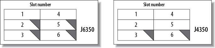
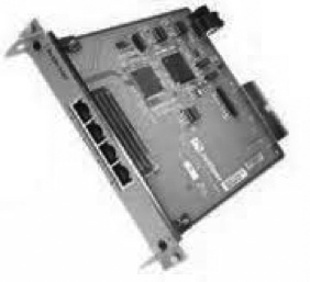
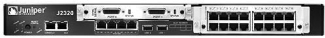
A J-series router does not contain any FPCs but does have PIM slots that are represented by the variable F. All fixed-port slots are always assigned slot 0, and PIM slots are assigned 1–6 numbering from top to bottom and left to right (see Figure 4-3).
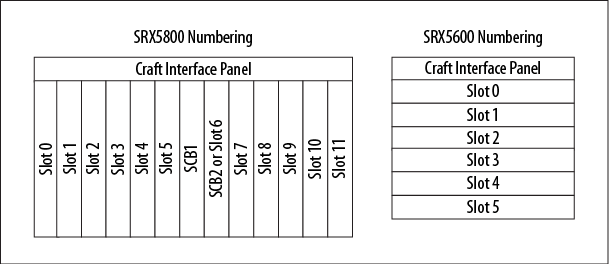
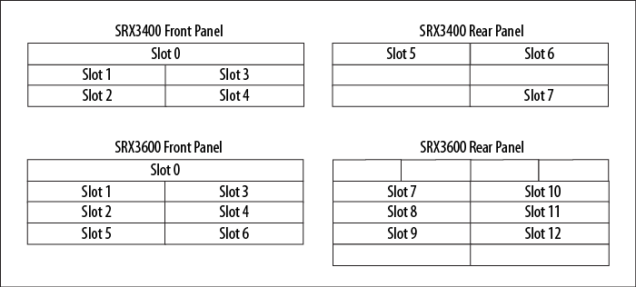
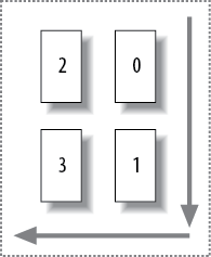
The SRXs support IOCs, not FPCs, and the slot numbers are dependent on the model types. For the SRX5800 series, the IOCs are mounted vertically and are numbered left to right, starting at slot 0, whereas the SRX5600s are numbered from top to bottom (see Figure 4-4).
The SRX 3000 series are numbered in two rows, front and rear (Figure 4-5). There are limitations on where IOCs can be placed in the chassis; refer to the hardware guides for these locations.
The branch office SRX series are numbered like the J-series routers, with the fixed interfaces on slot 0 and the remaining interfaces numbered in a left to right, top to bottom manner.
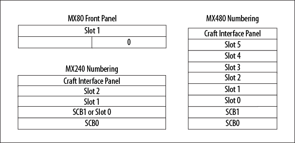
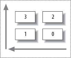
The MXs support interfaces on the dense port concentrators (DPCs) and modular port concentrators (MPCs). These are inserted into slots of the MX chassis. Similar to the SRX line, the MX slot-numbering system is model dependent. The MX960 is numbered identically to the SRX5800, whereas the MX480, MX240, and mid-range MXs are numbered from bottom to top (see Figure 4-6).
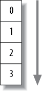
The next part of the interface name is the PIC slot number, represented by the variable P. In M-series routers, four PICs can fit into a single FPC slot. The slot numbers begin at 0 and continue to the final slot, 3. In M-series routers, the direction of PIC slot numbering depends on whether the chassis slots are vertically or horizontally aligned. In a vertically aligned M-series router, the PIC slot number is counted from top to bottom, as shown in Figure 4-7.
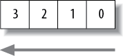
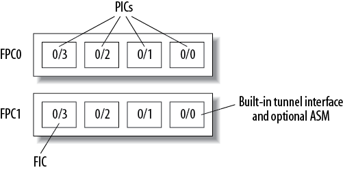
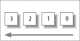
PIC slot numbering in horizontally aligned systems such as the M7i and M10i is a little less standard. In these systems, the PIC slot numbering goes from right to left, starting at 0 and ending at slot 3, as shown in Figure 4-8. The M7i’s second FPC slot contains only two possible PIC slot numbers, and as shown in Figure 4-9, slot 2 is used for the built-in tunnel interface, or Adaptive Services Module (ASM), and slot 3 is used for the fixed Ethernet interfaces.
In the SRX and MX devices, the PIC identifiers are based on the type of cards used. For the full-size slot cards (IOCs and DPCs), there are four PICs assigned to the slot (0, 1, 2, 3) in a top to bottom, left to right fashion when the cards are held vertically. For the smaller cards (MICs, PIMs, etc.), there are no PIC slots; thus, the interface naming (F) convention is always set to a value of 0.
Note
It seems counterintuitive that PIC slot numbering is counted from right to left. The reason harkens back to the first routers (M40), which were vertically aligned FPC slots with PIC slot numbering from top to bottom. Next came the horizontally aligned FPC slot (M20), which was essentially a vertically aligned router turned on its side, which caused the PIC slot to shift to right to left.
The last part of the interface name is represented by the variable T, or the actual physical port number. M-series routers have port numbers with a variety of schemes, depending on the PIC and the router model (horizontal versus vertical slots). For vertical FPC routers (m40e, M320), port numbers start from the top right and continue from the bottom to the top and then move right to left. For horizontal FPC routers (m20, m7i, m10i), port numbers start from the bottom right and then move right to left and from the bottom to the top. It’s easier to see by examining Figures 4-10 through 4-13, which show this sequence in the different chassis types.
Note
To avoid any confusion or spontaneous brain combustions, remember that the port number is always written on the PIC itself.
Note
The fixed Ethernet ports on the M7i follow the convention of Figure 4-13 and count from right to left, starting at port 0.
Port numbers are greatly simplified in J-series routers and Branch Office SRXs, as all ports are always numbered from left to right. This includes ports on a PIM (see Figure 4-14) as well any fixed ports on the chassis (see Figure 4-15).
Here are a few M-series example interfaces:
se-1/0/0Serial interface in FPC slot 1, PIC slot 0, and port 0
fe-0/2/1Fast Ethernet interface in FPC slot 0, PIC slot 2, and port 2
t1-1/0/1T1 interface in FPC slot 1, PIC slot 0, and port 1
Interfaces also have a logical portion of the name represented by
either a unit number or a channel number. A logical unit is a number that represents
the subinterface properties of the router and can be configured in the
range of 0–16,385. This is designated by a period (.) in the interface name. For
example:
ge-0/0/0.0Unit 0 configured on the Gigabit Ethernet interface
e3-1/0/2.12Unit 12 configured on the
e3interface
The other logical division could be a channel number—for
example, when breaking up a T1 interface into multiple DS0 channels
(up to 24). Channel values are represented using a colon (:). For example:
ct-1/1/2:14Channel 14 on a channelized T1 interface
We will cover logical units in depth in Logical Properties.
Get Junos Enterprise Routing, 2nd Edition now with the O’Reilly learning platform.
O’Reilly members experience books, live events, courses curated by job role, and more from O’Reilly and nearly 200 top publishers.

