Over the years, the importance of data communication has closely paralleled that of computing. In fact, most individuals are completely unaware of just how often data communications networks affect and enable our daily lives. Network technologies are ubiquitous to the point where a modern car has more processing power than a 1960s-era mainframe, along with several communications networks that control everything about the vehicle’s operation, from its chipped key ignition security, engine fuel/air mixture, and transmission shift points to the sensing and reporting of low tire pressure.
The modern world is hooked on computing, and in this addiction data networks are like a drug in the sense that most PC users find their machines rather dull and bordering on boring when their Internet access is down.
In fact, given the easy access we all have to nearly the sum of man’s knowledge (typically for free), the Internet and its World Wide Web make activities such as writing technology books seem rather old hat. But the amount of background information regarding general data communications concepts, local area network (LAN) technologies, and the TCP/IP protocol suite, which makes all of humankind’s knowledge available and easy to find, is still an invaluable library. It’s the library that enables the digital libraries. And so we start right here.
The primary goal of this book is to document the application and use of Juniper Networks EX switches in a number of LAN and interoperation scenarios. The coverage has already jeopardized our editor’s budgeted page count, which leaves us little room given that we wrote this chapter last and we are a bit tired and in dire need of sunshine. Therefore, we make no attempt in this chapter to re-create the “complete history of networking and LAN technologies” wheel.
Instead, this chapter’s goal is to provide an extremely targeted review of networking and LAN history, including internetworking principles related to LAN interconnect. Aside from an irreverent take on history for which the authors apologize beforehand (did we mention we saved this chapter for last?), what follows is also an extremely focused targeting of key principles that you should understand before moving on to the remainder of this book.
There aren’t a lot of pages, but it’s a fun, informative, and action-packed ride; trust us, both you and the trees are better for it.
The topics covered in this chapter include:
Networking and OSI overview
Ethernet technologies
The TCP/IP protocol suite
LAN interconnection
A network can be defined as two or more entities with something to say that is not already known to the intended recipients, and a channel or medium over which to convey this information. Simple enough, right?
Network technologies, much like fashions, seem to flare in popularity and then quietly fade away in favor of the next thing. At one point in the dark past of networking, users were compelled to source their network gear from a single vendor, oftentimes the same vendor that provided the data processing equipment. This was due to a lack of open standards that resulted in vendor-proprietary solutions for both the hardware and networking protocols.
Although good for the vendor, a single source for anything is generally bad for economics, and in some cases it can also hamper innovation and performance; after all, if a vendor has you locked into its solution, there may be little motivation for the vendor to spend money on research and development in an effort to improve the basic technology. Nope, users wanted to be able to select from best-of-breed solutions, ones that optimize on performance or price, while still enjoying end-to-end interoperability.
Enter the Open Systems Interconnection (OSI) model, which we detail in the next section.
The OSI model, and the International Organization for Standardization (ISO) suite of protocols that were originally based on the model, failed to see much adoption. As evidence, consider GOSIP. The Government Open Systems Interconnection Profile was first published in 1990, and essentially stated that all U.S. government communications networks must be OSI-compliant for consideration in networking bids. This was a big deal, and in theory it sounded the death knell for vendor-proprietary solutions. It was to include the U.S. Department of Defense’s (DoD) ARPANET (Advanced Research Projects Agency Network) protocols; e.g., TCP/IP, which at the time was the de facto multivendor interoperability solution. Given this level of backing, it is hard to understand how OSI/ISO could fail. The answers are multifaceted:
- The OSI protocols were slow to market/produced no products
The best ideas in the world are not very useful if they have no tangible manifestation in reality. Many of the official OSI protocols were never fully implemented and most were never deployed in production networks. Ironically, the OSI layers that did have products tended to function at or below Layer 4, which is just where existing technologies (i.e., TCP/IP) already existed and could be used as models. Stated differently, TCP/IP has a Network layer (IP), and so did the OSI model; it was called Connectionless Network Service (CLNS). The TCP stack does not have a true Session or Presentation layer, and it’s in these very upper layers where it seems the ISO bit off more than it could shove into a Layer 3 packet, so to speak.
- The OSI protocols were overtly complex and suffered from a slow development velocity
The OSI protocols attempted to go above and beyond existing network functionality. In effect, it was a protocol for the world’s current and future needs. This was a fine aspiration, but trying to solve every known or projected issue, all at once and in a worldwide forum, was just too hard. The resulting standards were too complicated or too incomplete to implement, especially when TCP/IP was already working.
- The IETF is too practical, and far, far too nimble
The Internet Engineering Task Force (IETF), which produces Internet RFCs and drafts, uses a guiding principle known as “rough consensus and running code”. The ability to move forward with working solutions without being bogged down in international law and geopolitics means that IETF standards significantly outpace their international counterparts, and are typically backed by a working implementation to boot! In contrast, the ITU/CCITT, which produced key ISO standards such as X.25 and B-ISDN in I.361, would meet every four years to make updates and solve problems. In theory, the world was supposed to patiently await their collective wisdom; in reality, IP simply ran the whole process over and never looked back to see what that bump in the road even was.
Basically, you could summarize all of these reasons as “The world already had a workable set of interoperability protocols known as TCP/IP, and the cost of waiting for official standards, which in the end always seemed to lack parity with the latest IP offerings anyway, was simply too jagged a pill to swallow.”
So, why are we (seemingly) wasting your invaluable time with a discussion of a grand failure? The answer is because although the OSI protocol stack itself failed, the related reference model lives on as a common way of expressing what role some networking device performs. The OSI model sought to partition the challenges of end-to-end communications among dissimilar machines into a layered approach, in which the protocol options, roles, and responsibilities for each layer were clearly defined.
Figure 1-1 shows the venerable OSI model in all its seven-layer glory, along with some selected protocol options for each layer. Note that upper layers were the least well defined, and few saw any production network use.
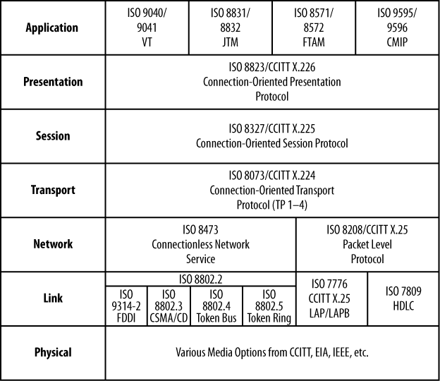
Key points about the model are:
Each layer interacts with a peer layer, which may be at the end of the link or at the actual receiver. In practical context, this generally means that a given layer adds some protocol header, and maybe a trailer, which is then acted upon and removed by the remote peer layer.
Some layers have a link-level scope whereas others have an end-to-end scope. A communications path can contain numerous independent links, but no matter how far-flung its constituent links are, it relies on a single Transport layer entity that exists only in the endpoints.
Each layer provides a service to the layer above it, and receives services from the layers below.
There is general modularity that provides options and the ability to “mix and match” specific technologies at a given layer. The specifics of each layer are opaque to those above and below it, as only service semantics are defined between the layers. This means that any LAN technology could be used to provide Link layer services to the Network layer, and in fact the ISO Connectionless Network Layer Service (CNLS) Network layer protocol could operate over Token Ring (802.5), CSMA/CD (802.3), and even Token Bus (802.4).[1] It should be noted that each such LAN technology typically came with its one slew of Layer 1 options, such as coaxial cable, twinaxial cable, or unshielded twisted pair (UTP).
As noted previously, a layered model works by using a divide-and-conquer approach, with each layer chipping in to do its part. The main function of each layer is as follows:
- Physical layer
The Physical layer is where the bits meet the road, so to speak. All communications systems require one. Layer 1 places bits onto the transmission medium for transmit, and pulls them off for receipt. It cares not what those bits mean, but some Physical layers have framing and/or Forward Error Correction (FEC) that allows them to detect problems and in some cases act better than they really are. Bits are the Protocol Data Units (PDUs) sent at Layer 1. EIA-232, SONET, V.32bis modems, and 1000Base-T are examples of Layer 1 technologies.
- Link layer
The Link layer deals with frames. It adds a header and trailer to frame upper-layer traffic, and generally provides link-by-link error detection. Some Link layers also provide error correction and multipoint addressing, as well as multiprotocol support through a type indication. Frames are the PDUs sent at Layer 2. Frame Relay and HDLC, as well as LAN MAC frames, are examples of Layer 2 technologies.
- Network layer
The Network layer is the first end-to-end layer. It can be said that a Network layer packet passes pretty much as it was sent, all the way to the remote endpoint. The Network layer identifies endpoints (not the next Link layer hop), and may provide error detection/correction, protocol identification, fragmentation support, and a Type of Service (ToS) indication. Packets (or datagrams) are the PDUs sent at Layer 3. IP is a Network layer, as is X.25.
Note
X.25 is technically a Layer 3 packet protocol. When used to support IP it functions more as a link between two entities. When sending IP over X.25 it can be said that there are two Network layers, but in this context IP is seen as the real Layer 3 as its endpoints may lie beyond the endpoints of the X.25 connection. Much of the same is true of other connection-oriented technologies, such as the Public Switched Telephone Network (PSTN) in analog form and its digital cousin, the Integrated Services Digital Network (ISDN).
- Transport layer
The Transport layer deals with end-to-end error control and the identification of the related application process through ports (sockets). This layer may also perform connection establishment, sequencing, flow control, and congestion avoidance. The term Service Data Unit (SDU) is often used to describe what is sent or received when dealing with Layer 4 or higher. In the TCP/IP model, segments are the PDUs sent at Layer 4.
- Session layer
The Session layer deals with session establishment, synchronization, and recovery. Given that we are now in the realm of things that never really happened, it’s hard to say what this means. TCP/IP has no official Session layer, but protocols such as Fault-Tolerant Overlay Protocol (FTOP) have a user sign-in phase.
- Presentation layer
The Presentation layer deals with application-specific semantics and syntax. In theory, this layer can convert to some machine- and application-independent format—say, ASN.1—upon transmission, and then back into the desired format upon reception. This is a pretty tough row to hoe, and seems much like a protocol converter in a layer. Again, there is no real example to give, other than that TCP/IP does use ASN.1 or HTML/XML data formats to help promote communications between dissimilar machines.
- Application layer
The Application layer is not the application. It’s the application’s interface or API into the communication’s stack. This is akin to a Windows or Unix socket in the TCP/IP context.
Figure 1-2 illustrates key concepts regarding layered protocol operation.
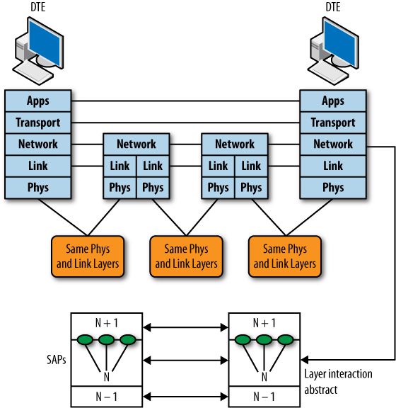
Figure 1-2 shows two communicating pieces of data terminal equipment (DTE) along with what appears to be a router-based form of interconnection, given the presence of Layer 3 in the intermediate nodes. The lower portion details generic layer interaction. Note that each layer communicates with a peer layer, which may be at the other end of the link, or at the far endpoint depending on the layer’s scope. Each layer accepts service requests from the layer above it, and in turn makes requests of the layer below.
The Network layer is the first end-to-end layer. As such, it’s technology-independent, meaning the same Network layer packet that is sent is pretty much the one received (minus the obligatory Time to Live [TTL] decrement designed to protect against routing loops). In contrast, Layers 1 and 2 vary by network technology type. Stations that communicate directly (i.e., those that share a link) must use compatible network technology. Stated differently, if the DTE on the left is running 10Base-T and is using Ethernet v2 framing, the first hop data circuit-terminating equipment (DCE)/router must be compatible. It may operate at 100 Mbps, given that repeaters and bridges can adapt Ethernet speeds, but it must support IP in Ethernet v2 encapsulation for communications to succeed across that link. If the connection is direct, the speed and duplex as well as other physical parameters must also match. The link between the two routers is a different link, and therefore does not have to be compatible with either DTE, as this link is not used for direct DTE communications.
There are many different kinds of network technologies and methods for communicating information among some set of stations. Generally speaking, a network is classified as being a wide area, local area, or metropolitan area technology (i.e., WAN, LAN, MAN). In some cases, the same technology can be used in all three environments. At one point this was the promise of ISDN, and then B-ISDN (ATM), but now it seems to be the domain of Ethernet, which holds more convergence promise than any other Link layer protocol.
Simply put, a LAN describes a set of nodes that communicate over a high-speed shared medium in a geographically confined area. A WAN can span the globe, tends to operate at lower speeds, and is often point-to-point (P-to-P) rather than multiaccess. Some multipoint WAN technologies are still in use; chief among them are Frame Relay and, in less developed parts of the world, the old standby, X.25.
The exchange of information between endpoints can occur in one of several ways:
- Point-to-point
As its name implies, this mode involves two endpoints, one as a source and the other as the recipient. Many WAN technologies are P-to-P. Modern P-to-P technologies are full duplex (FD), which means that both ends can send and receive simultaneously.
- Multipoint
Multipoint topologies are often associated with WANs. Historically, a multipoint technology describes a hub-and-spoke (sometimes called star) arrangement whereby a central site can send to all remote sites at the same time, but each remote site is allowed to send back only to the central site, à la IBM’s polled Synchronous Data Link Control (SDLC) protocol. Multipoint also refers to virtual circuit technologies such as Frame Relay and ATM that allow a single physical interface to be used to send to multiple destinations by using the correct circuit identifier (i.e., a Frame Relay DLCI or ATM VCI).
- Broadcast
A broadcast network uses shared media or some replication function to allow a single transmission to be seen simultaneously by all attached receivers. LANs always operate in a broadcast manner, making this one of their defining characteristics. Note that the use of switches (bridges) or routers isolates the broadcast domain, a technique used for both performance and security reasons.
Broadcast networks can operate in simplex, half-duplex (HD), or FD mode based on specifics.
- Non-Broadcast Multiple Access (NBMA)
An NBMA network is a form of virtual-circuit-based topology that does not permit true broadcast, but by virtue of having a virtual circuit to every other endpoint, an NBMA network can emulate broadcast functionality by sending the same message multiple times over each of its locally defined virtual circuits.
NBMA networks can operate in simplex, HD, or FD mode based on specifics. Practically all modern network technologies are now FD anyway, but some distribution systems are inherently simplex.
After the dust settled on the past 40 years of data networking, we may be so bold as to say that a few key trends have emerged:
OSI is dead, and we can only hope it’s resting peacefully, as the chip—nay, PDU—that it bears upon its shoulder would make for one nasty ghost.
IP is the dominant convergence technology that serves as the basis for everything from interactive data to email to telemedicine, virtual reality, and even old-school services such as telephony and many television distribution systems. There appears to be no serious threat to this venerable workhorse on the near horizon, except maybe its younger sibling, IPv6, which is creeping into more and more networks each day.
Ethernet rules the LANs, and most MANs, and is also being seen in long-haul WANs as part of Layer 2 virtual private network (VPN) services (that typically ride over IP-enabled Multiprotocol Label Switching, or MPLS, networks), or as native Ethernet as part of a PBB or long-haul SONET/SDH transport. Ethernet keeps getting faster (40 Gigabit Ethernet is now available) and cheaper, and updates such as Operational Administration and Maintenance (OAM) continue to extend its reach by providing it with some SONET-like maintenance and alarm-reporting capabilities. Ethernet is built into every PC, and virtually all broadband access is based on this Ethernet connection, attaching it to the DSL or cable modem used to access the service.
The next section focuses on modern Ethernet technologies as a primer for what is to come in the rest of this book. Today the term LAN switching is assumed to mean Ethernet. For those with a penchant for obscurity and a bit too much money and time on their hands, we hear you can find Token Ring Media Access Units (MAUs) on eBay at bargain basement prices these days; just be sure to get the high-speed 16 Mbps version. Running at 4 Mbps would look bad given that Ethernet made the 10 Mbps leap back in 1980, when the Digital Intel Xerox (DIX) consortium published the ESPEC v1 specification. There was even a (very) short-lived 32 Mbps “FD” Token Ring MAU available.
[1] Note that IEEE 802.x standards are prefixed with an additional “8” when adopted by the relevant OSI entity, thus ISO 8802.3 is equivalent to IEEE 802.3.
Get JUNOS Enterprise Switching now with the O’Reilly learning platform.
O’Reilly members experience books, live events, courses curated by job role, and more from O’Reilly and nearly 200 top publishers.

