Chapter 1. Introduction
The Unified Modeling Language (UML) is the standard modeling language for software and systems development. This statement alone is a pretty conclusive argument for making UML part of your software repertoire, however it leaves some questions unanswered. Why is UML unified? What can be modeled? How is UML a language? And, probably most importantly, why should you care?
Systems design on any reasonably large scale is difficult. Anything from a simple desktop application to a full multi-tier enterprise scale system can be made up of hundreds—and potentially thousands—of software and hardware components. How do you (and your team) keep track of which components are needed, what their jobs are, and how they meet your customers’ requirements? Furthermore, how do you share your design with your colleagues to ensure the pieces work together? There are just too many details that can be misinterpreted or forgotten when developing a complex system without some help. This is where modeling—and of course UML—comes in.
In systems design, you model for one important reason: to manage complexity. Modeling helps you see the forest for the trees, allowing you to focus on, capture, document, and communicate the important aspects of your system’s design.
A model is an abstraction of the real thing. When you model a system, you abstract away any details that are irrelevant or potentially confusing. Your model is a simplification of the real system, so it allows the design and viability of a system to be understood, evaluated, and criticized quicker than if you had to dig through the actual system itself. Even better, with a formal modeling language, the language is abstract yet just as precise as a programming language. This precision allows a language to be machine-readable, so it can be interpreted, executed, and transformed between systems.
To effectively model a system, you need one very important thing: a language with which the model can be described. And here’s where UML comes in.
What’s in a Modeling Language?
A modeling language can be made up of pseudo-code, actual code, pictures, diagrams, or long passages of description; in fact, it’s pretty much anything that helps you describe your system. The elements that make up a modeling language are called its notation . Figure 1-1 shows an example of a piece of UML notation.
Tip
There are references to the UML meta-model and profiles throughout this book. A more complete description of what the UML meta-model contains and why it is useful is available in Appendix B, but for now, just think of the UML meta-model as the description of what each element of notation means and a profile as a customization of that description for a specific domain (i.e., banking).
However, notation is not the whole story. Without being told that one of the boxes in Figure 1-1 represents a class, you wouldn’t necessarily know what it is, even though you might be able to guess. The descriptions of what the notation means are called the semantics of the language and are captured in a language’s meta-model.
A modeling language can be anything that contains a notation (a way of expressing the model) and a description of what that notation means (a meta-model). But why should you consider using UML when there are so many different ways of modeling, including many you could make up on your own?
Every approach to modeling has different advantages and disadvantages, but UML has six main advantages:
- It’s a formal language
Each element of the language has a strongly defined meaning, so you can be confident that when you model a particular facet of your system it will not be misunderstood.
- It’s concise
The entire language is made up of simple and straightforward notation.
- It’s comprehensive
It describes all important aspects of a system.
- It’s scaleable
Where needed, the language is formal enough to handle massive system modeling projects, but it also scales down to small projects, avoiding overkill.
- It’s built on lessons learned
UML is the culmination of best practices in the object-oriented community during the past 15 years.
- It’s the standard
UML is controlled by an open standards group with active contributions from a worldwide group of vendors and academics, which fends off “vendor lock-in.” The standard ensures UML’s transformability and interoperability, which means you aren’t tied to a particular product.
Detail Overload: Modeling with Code
Software code is an example of a potential modeling language where none of the detail has been abstracted away. Every line of code is the detail of how your software is intended to work. Example 1-1 shows a very simple class in Java, yet there are many details in this declaration.
package org.oreilly.learningUML2.ch01.codemodel;

public class Guitarist extends Person implements MusicPlayer {

   Guitar favoriteGuitar;

   public Guitarist (String name) {
      super(name);
   }

   // A couple of local methods for accessing the class's properties
   public void setInstrument(Instrument instrument) {
      if (instrument instanceof Guitar) {
         this.favoriteGuitar = (Guitar) instrument;
      }
      else {
         System.out.println("I'm not playing that thing!");
      }
   }

    public Instrument getInstrument(  ) {
      return this.favoriteGuitar;
   }

   // Better implement this method as MusicPlayer requires it
   public void play(  ) {
      System.out.println(super.getName(  ) + "is going to do play the guitar now ...");

      if (this.favoriteGuitar != null) {
         for (int strum = 1; strum < 500; strum++) {
            this.favoriteGuitar.strum(  );
         }
         System.out.println("Phew! Finished all that hard playing");
      }
      else {
         System.out.println("You haven't given me a guitar yet!");
      }
   }

   // I'm a main program so need to implement this as well
   public static void main(String[] args) {
      MusicPlayer player = new Guitarist("Russ");
      player.setInstrument(new Guitar("Burns Brian May Signature"));
      player.play(  );
   }
}
Example 1-1 shows all of the information about the Guitar class, including inheritance relationships to other classes, member variables involving other classes, and even implementation details for the methods themselves.
What’s wrong with using software source code as your model? All of the details are there, every element of the language’s notation has meaning to the compiler, and with some effective code-level comments, such as JavaDoc, you have an accurate representation of your software system, don’t you?
The truth is that you haven’t actually modeled anything other than the software implementation. The source code focuses only on the software itself and ignores the rest of the system. Even though the code is a complete and (generally) unambiguous definition of what the software will do, the source code alone simply cannot tell you how the software is to be used and by whom, nor how it is to be deployed; the bigger picture is missing entirely if all you have is the source code.
As well as ignoring the bigger picture of your system, software code presents a problem in that you need to use other techniques to explain your system to other people. You have to understand code to read code, but source code is the language for software developers and is not for other stakeholders, such as customers and system designers. Those people will want to focus just on requirements or perhaps see how the components of your system work together to fulfill those requirements. Because source code is buried in the details of how the software works, it cannot provide the higher level abstract views of your system that are suitable for these types of stakeholders.
Now imagine that you have implemented your system using a variety of software languages. The problem just gets worse. It is simply impractical to ask all the stakeholders in your system to learn each of these implementation languages before they can understand your system.
Finally, if your design is modeled as code, you also lose out when it comes to reuse because design is often reusable whereas code may not be. For example, reimplementing a Java Swing application in HTML or .NET is much simpler if the design is modeled rather than reverse engineering the code. (Reverse engineering is extracting the design of a system from its implementation.)
All of these problems boil down to the fact that source code provides only one level of abstraction: the software implementation level. Unfortunately, this root problem makes software source code a poor modeling language.
Verbosity, Ambiguity, Confusion: Modeling with Informal Languages
At the opposite end of the spectrum from complete and precise source code models are informal languages. Informal languages do not have a formally defined notation; there are no hard and fast rules as to what a particular notation can mean, although sometimes there are guidelines.
A good example of an informal language is natural language. Natural language—the language that you’re reading in this book—is notoriously ambiguous in its meaning. To accurately express something so that everyone understands what you are saying is at best a challenge and at worst flat-out impossible. Natural language is flexible and verbose, which happens to be great for conversation but is a real problem when it comes to systems modeling.
The following is a slightly exaggerated but technically accurate natural language model of Example 1-1:
Guitaristis a class that contains six members: one static and five non-static.Guitaristuses, and so needs an instance of,Guitar; however, since this might be shared with other classes in its package, theGuitarinstance variable, calledfavoriteGuitar, is declared asdefault.
Five of the members within
Guitaristare methods. Four are not static. One of these methods is a constructor that takes one argument, and instances ofStringare calledname, which removes the default constructor.
Three regular methods are then provided. The first is called
setInstrument, and it takes one parameter, an instance ofInstrumentcalledinstrument, and has no return type. The second is calledgetInstrumentand it has no parameters, but its return type isInstrument. The final method is calledplay. Theplaymethod is actually enforced by theMusicPlayerinterface that theGuitaristclass implements. Theplaymethod takes no parameters, and its return type isvoid.
Finally,
Guitaristis also a runable program. It contains a method that meets the Java specification for amainmethod for this reason.
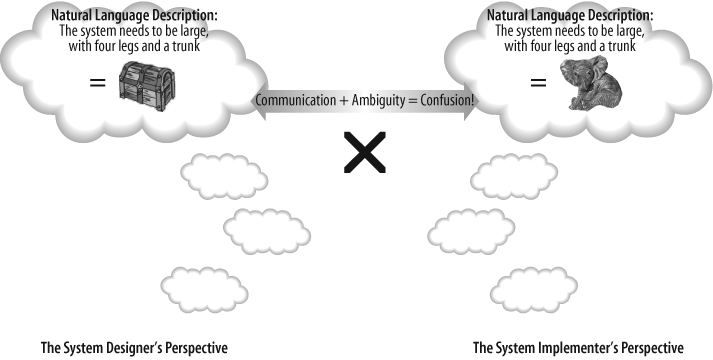
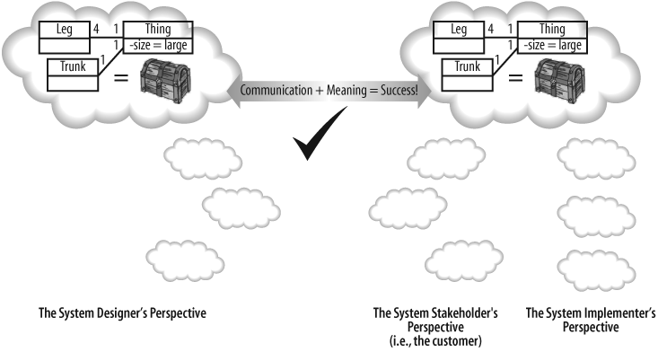
If you take a hard look at this definition, you can see problems everywhere, almost all resulting from ambiguity in the language. This ambiguity tends to result in the, “No, that’s not what I meant!” syndrome, where you’ve described something as clearly as possible, but the person that you are conveying the design to has misunderstood your meaning (see Figure 1-2).
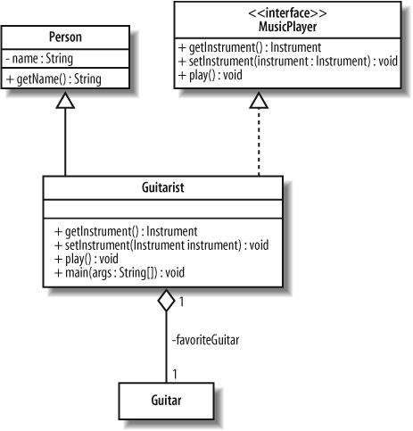
The problems with informal languages are by no means restricted to written languages. The same description of Guitarist might be presented as a picture like that shown in Figure 1-3.
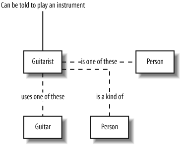
Figure 1-3 is another example of an informal language, and it happens to be a notation that I just made up. It makes perfect sense to me, but you could easily misinterpret my intentions.
As with the natural language model, all of the details are present in Figure 1-3’s picture, but without a definition of what the boxes, connections, and labels mean, you can’t be sure about your interpretation (or mine!).
Tip
So, why does any of this matter if your team has a home-grown modeling technique it’s been using for years and you all understand what each other means? If you ever have to show your design to external stakeholders, they might become frustrated trying to understand your home-grown symbols, when you could have used a standard notation they already know. It also means you don’t have to learn a new modeling technique every time you switch jobs!
The basic problem with informal languages is that they don’t have exact rules for their notation. In the natural language example, the meanings of the model’s sentences were obscured by the ambiguity and verbosity of the English language. The picture in Figure 1-3 may not have suffered from quite the same verbosity problems, but without knowing what the boxes and lines represent, the meaning of the model was left largely to guesswork.
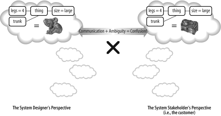
Because informal languages are not precise, they can’t be transformed into code as a formal language can. Imagine if Figure 1-3 had a set of formal rules; then you could generate code that implemented the classes for Guitarist, Person, and so on. But this is impossible without understanding the rules. Unfortunately, informal languages will always suffer from the dual problem of verbosity and ambiguity, and this is why they are a poor—and sometimes extremely dangerous—technique for modeling systems, as shown in Figure 1-4.
Tip
Although natural language is dangerously ambiguous, it is still one of the best techniques for capturing requirements, as you will see when you learn about use cases in Chapter 2.
Getting the Balance Right: Formal Languages
You’ve now seen some of the pitfalls of using a too-detailed language for modeling (source code) and a too-verbose and ambiguous language for modeling (natural language). To effectively model a system—avoiding verbosity, confusion, ambiguity, and unnecessary details—you need a formal modeling language .
Ideally, a formal modeling language has a simple notation whose meaning is well-defined. The modeling language’s notation should be small enough to be learned easily and must have an unambiguous definition of the notation’s meaning. UML is just such a formal modeling language.
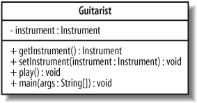
Figure 1-5 shows how the code structure in Example 1-1 can be expressed in UML. For now, don’t worry too much about the notation or its meaning; at this point, the UML diagram is meant to be used only as a comparison to the informal pictorial and natural language models shown previously.
Even if you don’t yet understand all of the notation used in Figure 1-5, you can probably start to grasp that there are some details present in the code—see Example 1-1—that are not modeled here. For example, the specific implementation of the play( ) method has been abstracted away, allowing you to visualize the code’s structure without excess clutter.
The best thing about having modeled the system using UML is that the notation in Figure 1-5 has a specific and defined meaning. If you were to take this diagram to any other stakeholder in your system, provided he knows UML, the design would be clearly understood. This is the advantage of using formal languages for modeling as shown in Figure 1-6.
Why UML 2.0?
The first version of UML allowed people to communicate designs unambiguously, convey the essence of a design, and even capture and map functional requirements to their software solutions. However, the world changed more fundamentally with the recognition that systems modeling, rather than just software modeling, could also benefit from a unified language such as UML.
The driving factors of component-oriented software development, model-driven architectures, executable UML, and the need to share models between different tools placed demands on UML that it had not originally been designed to meet.
Also, UML 1.x and all of its previous revisions were designed as a unified language for humans. When it became important for models to be shared between machines—specifically between Computer Aided Systems Engineering (CASE) tools—UML 1.x was again found wanting. UML 1.x’s underlying notation rules and its meta-model were (ironically) not formally defined enough to enable machine-to-machine sharing of models.
Although UML 1.5 described a system fairly well, the model describing the model—the meta-model—had become patched and overly complex. Like any system that has an overly complex design, and is fragile and difficult to extend, UML had become overly complex, fragile, and difficult to extend; it was time for a re-architecture.
The designers of UML 2.0 were very careful to ensure that UML 2.0 would not be too unfamiliar to people who were already using UML 1.x. Many of the original diagrams and associated notations have been retained and extended in UML 2.0 as shown in Table 1-1. However, new diagram types have been introduced to extend the language just enough so that it can support the latest best practices.
With Version 2.0, UML has evolved to support the new challenges that software and system modelers face today. What began many years ago as a unification of the different methods for software design has now grown into a unified modeling language that is ready and suitable to continue to be the standard language for the myriad of different tasks involved in software and systems design.
|
Diagram type |
What can be modeled? |
Originally introduced by UML 1.x or UML 2.0 |
To learn about this diagram type, go to... |
|
Use Case |
Interactions between your system and users or other external systems. Also helpful in mapping requirements to your systems. |
UML 1.x | |
|
Activity |
Sequential and parallel activities within your system. |
UML 1.x | |
|
Class |
Classes, types, interfaces, and the relationships between them. |
UML 1.x |
Chapters 4 and 5 |
|
Object |
Object instances of the classes defined in class diagrams in configurations that are important to your system. |
Informally UML 1.x | |
|
Sequence |
Interactions between objects where the order of the interactions is important. |
UML 1.x | |
|
Communication |
The ways in which objects interact and the connections that are needed to support that interaction. |
Renamed from UML 1.x’s collaboration diagrams | |
|
Timing |
Interactions between objects where timing is an important concern. |
UML 2.0 | |
|
Interaction Overview |
Used to collect sequence, communication, and timing diagrams together to capture an important interaction that occurs within your system. |
UML 2.0 | |
|
Composite Structure |
The internals of a class or component, and can describe class relationships within a given context. |
UML 2.0 | |
|
Component |
Important components within your system and the interfaces they use to interact with each other. |
UML 1.x, but takes on a new meaning in UML 2.0 | |
|
Package |
The hierarchical organization of groups of classes and components. |
UML 2.0 | |
|
State Machine |
The state of an object throughout its lifetime and the events that can change that state. |
UML 1.x | |
|
Deployment |
How your system is finally deployed in a given real-world situation. |
UML 1.x |
Models and Diagrams
Many newcomers to UML focus on the different types of diagrams used to model their system. It’s very easy to assume that the set of diagrams that have been created actually are the model. This is an easy mistake to make because when you are using UML, you will normally be interacting with a UML tool and a particular set of diagrams. But UML modeling is not just about diagrams; it’s about capturing your system as a model—the diagrams are actually just windows into that model.
A particular diagram will show you some parts of your model but not necessarily everything. This makes sense, since you don’t want a diagram showing everything in your model all at once—you want to be able to split contents of your model across several diagrams. However, not everything in your model needs to exist on a diagram for it to be a part of your model.
So, what does this mean? Well, the first thing to understand is that your model sits behind your modeling tool and diagrams as a collection of elements. Each of those elements could be a use case, a class, an activity, or any other construct that UML supports. The collection of all the elements that describe your system, including their connections to each other, make up your model.
However, if all you could do was create a model made up of elements, then you wouldn’t have much to look at. This is where diagrams come in. Rather than actually being your model, diagrams are used merely as a canvas on which you can create new elements that are then added to your model and organize related elements into a set of views on your underlying model.
So, when you next use your UML tool to work with a set of diagrams in UML notation, it is worth remembering that what you are manipulating is a view of the contents of your model. You can change elements of your model within the diagram, but the diagram itself is not the model—it’s just a useful way of presenting some small part of the information your model contains.
“Degrees” of UML
UML can be used as much or as little as you like. Martin Fowler describes three common ways that people tend to use UML:
- UML as a sketch
Use UML to make brief sketches to convey key points. These are throwaway sketches—they could be written on a whiteboard or even a beer coaster in a crunch.
- UML as a blueprint
Provide a detailed specification of a system with UML diagrams. These diagrams would not be disposable but would be generated with a UML tool. This approach is generally associated with software systems and usually involves using forward and reverse engineering to keep the model synchronized with the code.
- UML as a programming language
This goes directly from a UML model to executable code (not just portions of the code as with forward engineering), meaning that every aspect of the system is modeled. Theoretically, you can keep your model indefinitely and use transformations and code generation to deploy to different environments.
The approach used depends on the type of application you’re building, how rigorously the design will be reviewed, whether you are developing a software system, and, if it is software, the software development process you’re using.
In certain industries, such as medical and defense, software projects tend to lean toward UML as a blueprint because a high level of quality is demanded. Software design is heavily reviewed since it could be mission-critical: you don’t want your heart monitoring machine to suddenly display the “blue screen of death.”
Some projects can get away with less modeling. In fact, some commercial industries find that too much modeling is cumbersome and slows down productivity. For such projects, it makes sense to use UML as a sketch and have your model contain some architectural diagrams and a few class and sequence diagrams to illustrate key points.
UML and the Software Development Process
When you are using UML to model a software system, the “degree of UML” you apply is partially influenced by the software development process you use.
A software development process is a recipe used for constructing software—determining the capabilities it has, how it is constructed, who works on what, and the timeframes for all activities. Processes aim to bring discipline and predictability to software development, increasing the chance of success of a project. Since UML is the language for modeling your software, it’s an important part of the software development process.
A few well-known software development processes include:
- Waterfall
The waterfall method attempts to pin down the requirements early in the project life cycle. After gathering requirements, software design is performed in full. Once the design is complete, the software is implemented. The problem with this method is that if a change in requirements occurs, the impact can be devastating.
- Iterative
Iterative methods attempt to address the shortcomings of the waterfall approach by accepting that change will happen and, in fact, embracing it. The Unified Process is a well-known iterative process. It consists of multiple phases, each phase containing some amount of the following activities: requirements, design, and implementation (coding). Iterative methods encompass a wider range of approaches (e.g., agile iterative processes), and they can range from using UML as sketch to using UML as blueprint.
- Agile methods
Agile methods use iterations in extremely short bursts and attempt to minimize risk by always having a working system of expanding capabilities. Methodologies under this category have introduced some of the more interesting development practices, such as pair programming and test-driven development. Agile methods emphasize using UML as a sketch.
Views of Your Model
There are a number of ways to break up your UML model diagrams into perspectives or views that capture a particular facet of your system. In this book, we use Kruchten’s 4+1 view model to help you show you how each diagram type plays a part in the overall model, as shown in Figure 1-7.
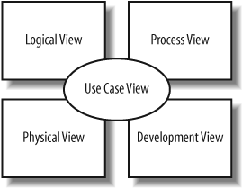
The 4+1 view model breaks down a model into a set of views, each capturing a specific aspect of your system:
- Logical view
Describes the abstract descriptions of a system’s parts. Used to model what a system is made up of and how the parts interact with each other. The types of UML diagrams that typically make up this view include class, object, state machine, and interaction diagrams.
- Process view
Describes the processes within your system. It is particularly helpful when visualizing what must happen within your system. This view typically contains activity diagrams.
- Development view
Describes how your system’s parts are organized into modules and components. It is very useful to manage layers within your system’s architecture. This view typically contains package and component diagrams.
- Physical view
Describes how the system’s design, as described in the three previous views, is then brought to life as a set of real-world entities. The diagrams in this view show how the abstract parts map into the final deployed system. This view typically contains deployment diagrams.
- Use case view
Describes the functionality of the system being modeled from the perspective of the outside world. This view is needed to describe what the system is supposed to do. All of the other views rely on the use case view to guide them—that’s why the model is called 4+1. This view typically contains use case diagrams, descriptions, and overview diagrams.
Each view offers a different and important perspective on your model. If you find yourself asking, “Why do I care about this?” as you read about a particular notation or diagram, refer to the view that the diagram or notation provides to understand why it is needed.
Tip
To learn more about Kruchten’s 4+1 view model, check out “Architectural Blueprints—The ’4+1’ View Model of Software Architecture” by Philippe Kruchten, at http://www3.software.ibm.com/ibmdl/pub/software/rational/web/whitepapers/2003/Pbk4p1.pdf. For an overview, visit http://www-128.ibm.com/developerworks/wireless/library/wi-arch11/.
A First Taste of UML
Before jumping into the different types of diagrams that make up UML, you need to know about two elements of UML notation that are used throughout a model: notes and stereotypes .
Notes
Notes allow you to enter additional comments that aren’t captured in your diagrams. You can write anything you want in a note to explain your diagram, similar to a comment in code. Notes are pictured with the folded rectangle notation as shown in Figure 1-8.

Notes can be placed on a diagram in isolation or attached to a specific part of the diagram as shown in Figure 1-9.
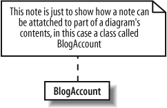
In this book, notes are used to explain something more about a particular diagram. Notes are just aids for the reader of a diagram; they don’t change the meaning of the diagram or the underlying model at all.
Stereotypes
Stereotypes signify a special use or intent and can be applied to almost any element of UML notation. Stereotypes modify the meaning of an element and describe the element’s role within your model.
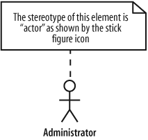
A stereotype sometimes has an associated icon, such as in Figure 1-10’s stick-figure actor symbol. To learn more about actors, see Chapter 2.
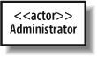
There isn’t always a special icon for a stereotype; sometimes they take up too much room and clutter a diagram. In these cases, the stereotype is shown using guillemots at either end of the stereotype name, as in «stereotype_name», shown in Figure 1-11. However, because guillemots require an extended character set, you can substitute them for angle brackets, as in <<stereotype_name>>.
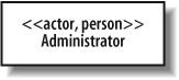
There is no limit to the number of stereotypes with which an element can be associated; sometimes you may end up specifying more than one stereotype, as shown in Figure 1-12.
The UML specification defines a set of “standard” or predefined stereotypes. Some of the more useful standard stereotypes include:
Stereotype applied to classes (see Chapters 4 and 5)
-
utility Represents a class that provides utility services through static methods, just as Java’s
Mathclass.
Stereotypes applied to components (see Chapter 12)
-
service A stateless, functional component that computes a value; could be used to represent a web service.
-
subsystem A large component that is actually a subordinate system of a larger system.
Stereotypes applied to artifacts (see Chapter 15)
-
executable A physical file that is executable, such as an .exe file.
-
file A physical file used by your system; this could be a configuration file such as a .txt file.
-
library A static or dynamic library file; you could use this to model .dll or .jar library files.
-
source A source file containing code, such as a .java or .cpp file.
Tagged values
Stereotypes can contain extra information that relates to the element to which they are applied. This extra information is specified using tagged values .
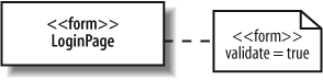
Tagged values are associated with a stereotype. Say you had an element in your model that represented a login page on a web site, and it was stereotyped as a form. The form stereotype needs to know whether it should validate the contents of the form or not in this case. This validation decision should be declared as a tagged value of the form stereotype because it is associated with the stereotype that is applied to an element, not with the element itself.
A tagged value is drawn on a diagram using a similar notation to notes, but the folded rectangle contains the name of any stereotypes and settings for any associated tagged values. The tagged value note is then attached to the stereotyped element using a dotted line with a circle at the element end, as shown in Figure 1-13. (This example was adapted from UML 2.0 in a Nutshell [O’Reilly].)
Tip
In UML 2.0, stereotypes and their tagged values are defined using profiles. To learn more about stereotypes and how to create roles for the elements of your model, see Appendix B.
Want More Information?
The next step is to jump into Chapter 2 and start learning UML. If you’re a bit of a history buff, then you can also check out a brief history of UML in Appendix C.
UML is a concise language but a big subject. As well as learning about UML, it’s worth reading through the tutorials and documentation available at the Object Management Group ’s web site, http://www.omg.org.
Get Learning UML 2.0 now with the O’Reilly learning platform.
O’Reilly members experience books, live events, courses curated by job role, and more from O’Reilly and nearly 200 top publishers.

