5.5 Performance
In this section the benefits from the uplink carrier aggregation are investigated, both theoretically and also based on the simulations. The gain mechanism is basically the same as in the downlink direction, but the limited (and now shared) transmission power makes some differences in the uplink direction. The following areas (the same as with the downlink carrier) are improved with the uplink carrier aggregation, as also studied in [1]:
- Load balancing;
- Resource sharing;
- Frequency domain joint scheduling over more than one frequency;
- More bandwidth for a given user resulting in a higher peak data rate.
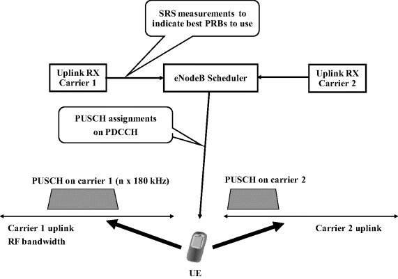
The load balancing and resource sharing is similar to the downlink. The eNodeB resources are now pooled on both carriers and load of the UEs with carrier aggregation can be shared on a 1 ms (TTI basis) on the two carriers. The use of Sounding Reference Signals (SRS) in the uplink now allows for uplink frequency domain scheduling, as shown in Figure 5.10. Alternatively the frequency domain scheduling can be done based on the interference measurements in the eNodeB. The eNodeB may configure the SRS patterns on each carrier as in earlier Releases as was discussed in Chapter 3, with the accuracy on each carrier depending then on the amount of SRS send on the uplink carriers in use.
Figure 5.10 Uplink frequency domain scheduling based on SRS transmission.

The uplink ...
Get LTE Advanced: 3GPP Solution for IMT-Advanced now with the O’Reilly learning platform.
O’Reilly members experience books, live events, courses curated by job role, and more from O’Reilly and nearly 200 top publishers.

