9.6 Coverage and Capacity
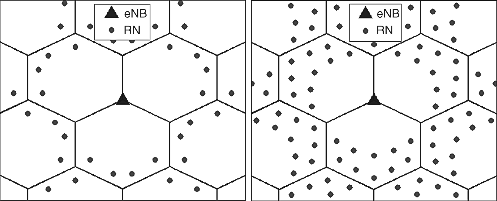
Two deployment scenarios are considered where 4 relay nodes are deployed in one tier at the cell edge as well as 10 relay nodes which are deployed in two tiers at the cell edge, as shown in Figure 9.22. The assumed power levels are 46 dBm for the eNodeBs and 30 dBm for the relay nodes.
Figure 9.22 Relay node deployment in one (4 relays) and two (10 relays) tiers.

9.6.1 Coverage Gain
The relay node deployment is considered in Release 10 mainly for coverage extension where relays are best deployed at (close to) the cell edge where users suffer from poor throughput and having a relay closer to these users can significantly boost their performance and thus the coverage.
In case the current eNodeB deployment does not meet the throughput requirements for the users located at the cell edge (Figure 9.23a), the traditional solution consists of increasing the density (Figure 9.23b) by deploying more eNodeBs. As alternative solution small nodes, like pico nodes or relay nodes, can be deployed at the cell edge (Figure 9.23c) such that the performance of the cell edge users is the same as increasing the density of eNodeBs. We define the scenarios in Figure 9.23b) and Figure 9.23c) as isoperformance scenarios when the performance of the cell edge users is the same [16].
Figure 9.23 Relay node deployment or increase of eNodeBs density to meet the performance requirements ...
Get LTE Advanced: 3GPP Solution for IMT-Advanced now with the O’Reilly learning platform.
O’Reilly members experience books, live events, courses curated by job role, and more from O’Reilly and nearly 200 top publishers.

