December 2011
Intermediate to advanced
96 pages
2h 1m
English
Start by putting two 8-pin headers (see Figure A-1) into the pin holes of the “digital” wing (the one with RX and TX pins). Use some poster putty such as Blu-Tack to hold pins in place (Figure A-2). Otherwise they will easily get misaligned when you are soldering them from the other side.

Figure A-1. Contents of the ScrewShield package
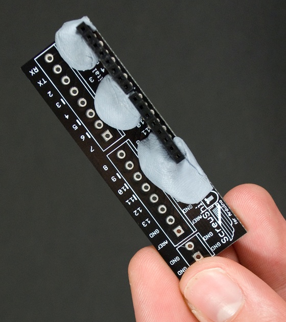
Figure A-2. Poster putty holds two 8-pin headers in place
Mount the wing to third-hand tool or similar (Figure A-3). You can’t hold it yourself while you are soldering, as you need one hand for soldering iron and other for the solder. Turn the wing upside down and solder the pins in place.
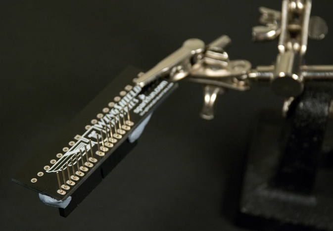
Figure A-3. Headers ready to be soldered
Now you need to do the same thing to the other wing. Secure the 6-pin headers with poster putty. Turn the wing upside down and solder (Figure A-4).
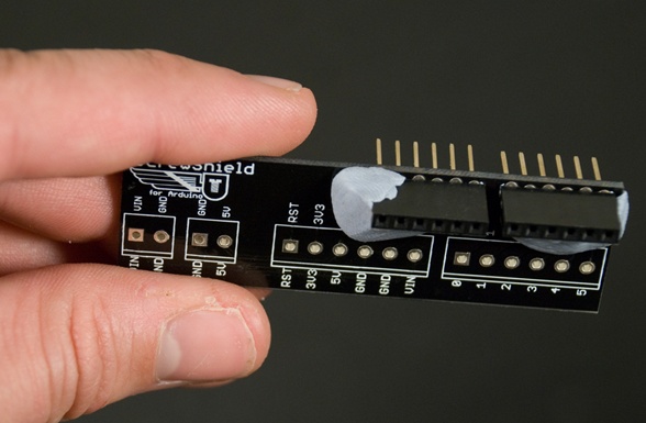
Figure A-4. “Analog” wing with 6-pin headers
The ScrewShield package includes a variety of terminal blocks. They can be connected by vertically sliding them together. Form two 6-pin blocks and two 8-pin blocks (Figure A-5).
Figure A-5. Forming two 6-pin blocks ...
Read now
Unlock full access


