Chapter 1. Getting Started with IOIO
IOIO (pronounced YoYo) is an input/output board for Android phones and tablets. It allows you to attach electronic devices to your Android phone using the USB connection. If you have a IOIO with the latest firmware, you can also communicate over Bluetooth if you attach a Bluetooth adapter to the IOIO.
In this chapter we will look at how to set up your computer and Android phone to use the IOIO and use the sample application that comes with the IOIO software to turn the “status” LED on and off for your phone.
What is IOIO?
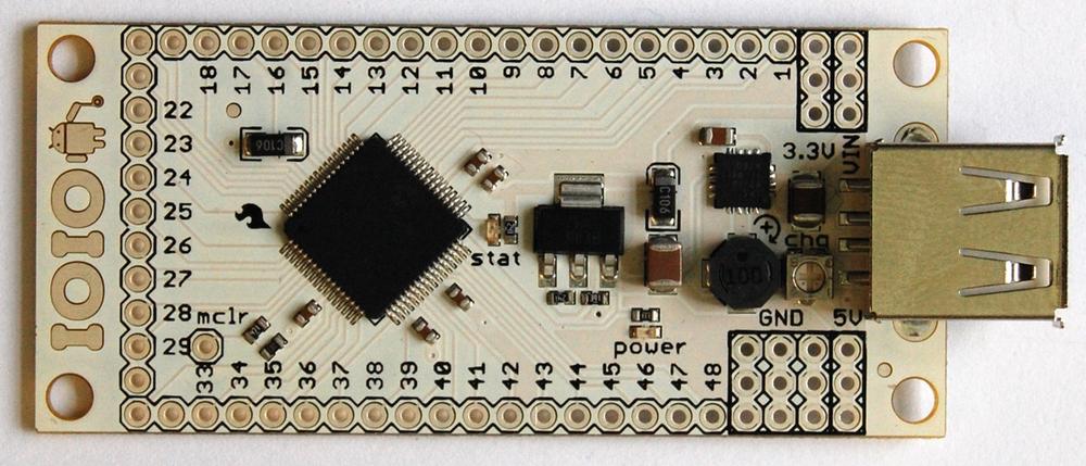
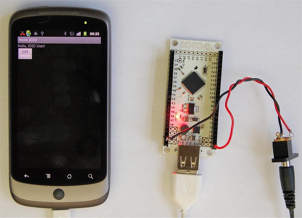
IOIO (Figure 1-1) is a product produced and sold by SparkFun (among others). It contains a PIC microcontroller and USB interface and a few other glue components to regulate the supply voltage etc. The whole project, both hardware and software is open source.
To make use of an IOIO, you will need:
An Android phone with USB lead
A Windows, Mac, or Linux computer
A power supply 5-15V DC offering at least 500mA
Since the IOIO comes without any sockets soldered to its connectors, we will attach some to it and make a power lead for it. To do this, you will also need the parts listed in Table 1-1.
| Quantity | Description | SparkFun SKU | Farnell code | Newark code |
1 | IOIO board | DEV-10748 | ||
2 | SIL Header socket strip | PRT-00115 | 1126603 | 52K3454 |
1 | 2.1mm Power socket | PRT-00119 | 1217038 | 97K6459 |
2 | single header pins | PRT-00116 | 1097954 | 93K5128 |
short lengths of red and black multicore wire | ||||
1 | 9V power supply | TOL-00298 | 1354815 | 97F7919 |
Android Phone
IOIO will work with a wide range of Android phones. Most Android phones with Android 1.5 or later will work with this board. Any new phone that you buy will have at least Android 2.1 on it.
The type of USB connection that you need is USB client. This is what the vast majority of regular Android phones will have. This takes the form of a little USB-micro B connector. However, some newer Android devices have USB host connection that usually looks like a regular USB socket such as you would find on a desktop computer. This type of connection is not compatible with IOIO.
When you use IOIO, you write the program on your computer and then transfer it to your phone using the USB connection. You can then unplug the USB lead from your computer and plug it into the IOIO so that your phone is now connected to the IOIO board. There is no actual programming of the IOIO board itself. The program runs on the phone, which communicates with the IOIO over USB or Bluetooth.
Computer
IOIO uses the same Integrated Development Environment that Google recommends for Android development—Eclipse. Eclipse isn’t required for either Android or IOIO, but it is the most common software used to create apps for them. Eclipse and the other software that you need are all available for Windows, Mac, and Linux.
Eclipse is fairly resource-hungry, so you will need a reasonably modern computer, or it will be slow and annoying to use. I use a 2.5GHz dual core Mac with 4GB and it works absolutely fine.
Power Supply
The IOIO does not take power from USB. So if you connect it to your phone with the USB lead, the power light on the IOIO will not illuminate.
The phone expects to receive charging power from the IOIO as if it were plugged into your computer, so you need to connect a power supply to the IOIO board. This may be a plug-in power supply or could be as simple as a small 9V battery. Although if you are connecting through USB rather than Bluetooth, a small 9V battery will not last long, as the charging current to the phone will soon empty it.
The projects in the following chapters use a mixture of power adapters and batteries.
None of the projects in this book, are very power-hungry and a 500mA (5W) supply is enough. However, the IOIO possesses a high-power voltage regulator, which means for more demanding projects, it can provide up to 1.5A at 5V. So, if you plan to use your IOIO to control high-power devices like motors and high-power LEDs, you may wish to buy say a 20W power supply. The rover project in Chapter 5 uses low-power motors, and is in any case battery-powered.
If you are looking for a power connector on the board, I’m sorry to say there isn’t one. We will need to do some soldering to the board to make the power connections. Alternatively, there is an area on the back of the board, behind the USB connector where a surface mount JST connector can be soldered. SparkFun supplies such a connector (PRT-08612) as well as a power socket adaptor (TOL-08734), but they are not necessary for the projects in this book.
We are going to solder sockets to the board so that we can do most of our later project work with little or no soldering.
Preparing Your IOIO Board
In this section, we will prepare the IOIO board to be used by the various projects in this book. To do this, you will need to buy the items in Table 1-1.
When you get your IOIO board, it will be completely naked with no connectors or visible means of connecting electronics or even a power supply. In the various projects in this book, we will need to make both power and electronic input and output connections. To do this, we must find a way of attaching wires to the connector pads.
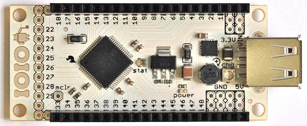
A convenient way to do this is to solder header strips to the two long sides of the IOIO. The projects in this book use only the first 20 connectors on each side and none of the connectors on the end. Figure 1-2 shows the board with the header sockets in place.
To solder the connectors, put them in place, then turn the board upside down so that its weight holds the sockets in position. Making sure that the sockets are straight, solder each connector in turn. When done, carefully check that there are no solder bridges between connectors.
For the power connection, we are going to make a short lead that has two header pins on one end and a standard 2.1mm low voltage power supply socket on the other end. This will allow us to drive the IOIO from a low-cost wall-wart type power supply (Figure 1-3).
The IOIO board has the Vin pin and GND pins on opposite sides of the board, across which power should be provided. This means that our lead will need to separate at the board end. Twisting the wires together helps neaten the lead.
It is a good idea to use red wire for the positive connection to the center connection of the 2.1mm socket and a black lead from the outside connector of the socket to the GND pin. Notice that on the IOIO board, we have a choice of three GND sockets. Any one will do when connecting up the power.
Having got this far, we can at least check that our board will power up, by connecting the external power supply. You should find that the “Power” LED will light, and if you connect a phone to the USB cable, you should see that its charging LED will light, indicating that the IOIO is actually supplying power to the phone.
If the phone does not start charging, then you can use a small screwdriver to adjust the trim-pot just behind the USB socket. This controls how much current is supplied to the phone. If it is set too low, then the phone may not detect that the IOIO is attached.
Warning
Most power supplies make the center pin of their 2.1mm plug the positive connection, but some adaptors, especially in the music world, are the other way around. So check the polarity before connecting up.
Installation
If you do not want to set your computer up to build your own IOIO apps, the IOIO apps used in the projects in this book are all available, ready built for download from the book’s website [http://www.ioiobook.com].
But if you want to write your own apps for IOIO or want to get a better understanding of how the apps work, you will need to follow the instructions below. You effectively need to install everything that you need for Android software development, and then some extra code specific to making apps that use IOIO.
Overall, the steps involved are:
Install Java.
Install Eclipse.
Install the Android SDK.
Install the Eclipse Android ADT Plugin.
Import the IOIO library and sample apps.
To install a suitable Java environment and Eclipse, see the instructions at [http://wiki.eclipse.org/Eclipse/Installation].
Once Eclipse is installed, install the Android SDK by following the instructions at [http://developer.android.com/sdk].
Instructions for installing the ADT Plugin for Eclipse can be found at [http://developer.android.com/sdk/eclipse-adt.html].
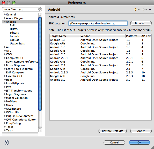
Once the ADT Plugin has been installed, you will need to tell Eclipse about the location of the Android SDK. To do this, open the Preferences panel in Eclipse and select Android on the lefthand side. In the SDK field location, browse to the root directory of the ADT that you just installed (Figure 1-4).
When we installed the ADT earlier, we installed only the basic framework. We now need to install packages for the Android platform versions that we want to use. You should at least install the platform that matches your phone version. Normally, any applications that you build with an earlier version of Android will still work on a phone with a more recent version. Select the version of Android that matches that of your phone.
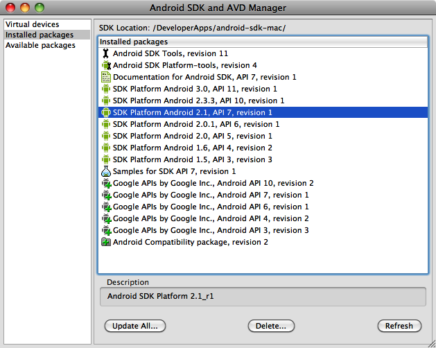
Platforms are added using a tool called the Android SDK and AVD Manager. This is launched from the Window menu in Eclipse, or by typing “android” from the Linux or Mac command lines. As you can see from Figure 1-5, the author has quite a few platforms installed. You can install as many as you like, because they will not conflict with each other.
If you want to use IOIO with the new Android Open Accessory framework, you will also need to install SDK Platform Android 2.2.2, API 10. Click on Available Packages to find packages to install. However, this is not necessary for the projects in this book.
Once your basic Android development setup is complete, you need to import all the IOIO sample projects and library from within Eclipse.
The first step is to download the zip file containing IOIOLib and the examples. You can find this at [https://github.com/ytai/ioio/wiki/Downloads].
Download the latest version. Version 3.10 and later have support for Bluetooth. The zip file will be called something like App-IOIO0310.zip.
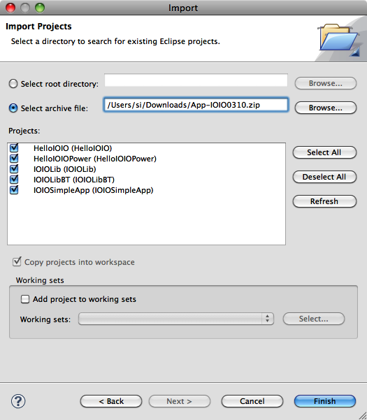
Next, from Eclipse, right-click in the Project Explorer area and select Import, then General and Existing Projects into Workspace (Figure 1-6). Click the radio button for Select Archive File. Then browse to the zip file you downloaded.
Include all the example projects, as although you only actually need HelloIOIO, IOIOLib and IOIOLibBT,→ it is useful to have the other projects as examples. The projects that you find here may vary as the IOIO software is updated.
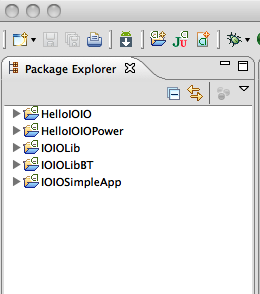
You will then have the entries shown in Figure 1-7 in your Project Explorer. If there is a red error cross next to any of the projects, go to the Project menu and select Clean to clean all the projects. This will normally remove any crosses. If it isn’t, try pasting the error message that you get into your search engine.
Hello IOIO
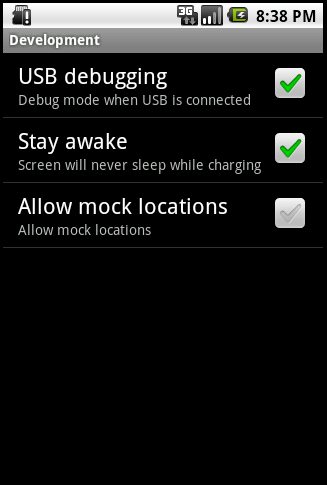
Open the first project in the list (HelloIOIO) and connect your phone to your computer with the USB lead. For the app to be installed onto your phone, you will need to make sure that USB debugging is turned on. You can find this option on your phone if you open Settings and then go to Applications and then Development (Figure 1-8).
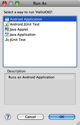
Select HelloIOIO in the Eclipse Project Explorer and then click on the green Play button on the toolbar. The first time you do this, you may get the dialog shown in Figure 1-9. Just select the option Android Application.
If your phone is connected correctly, the App will be installed and launched on it, so that you can now disconnect the computer end of the USB lead and plug it into the IOIO board, which should also be connected to your power supply (Figure 1-10).
Clicking on the button will turn the LED on the IOIO board on and off.
It is beyond the scope of this book to teach you Android and Java programming from scratch. However, the IOIO library is very nicely designed, and you should find that even if you have very little programming experience, you will be able to take the programs in this book and modify them for your own use.
In the HelloIOIO app, there are really just two files that do most of the work: MainActivity.java and main.xml.
MainActivity.java can be found under src/ioio/example/hello. This file contains the code that controls the one and only Activity in this project. In Android, an Activity is akin to a screen in other frameworks.
If you look at the top of this file, you will find:
public class MainActivity extends AbstractIOIOActivity {This tells us that we are creating a subclass of AbstractIOIOActivity, which will implement the IOIO framework behind the scenes for us, so we can just get on with the part of our project that is specific to this app.
This Java file has no information about how the user interface for this Activity is arranged. This is held in the template file main.xml, which is kept in res/layout:
<?xml version="1.0" encoding="utf-8"?>
<LinearLayout xmlns:android="http://schemas.android.com/apk/res/android"
    android:orientation="vertical"
    android:layout_width="fill_parent"
    android:layout_height="fill_parent"
    ><TextView
    android:layout_width="fill_parent"
    android:layout_height="wrap_content"
    android:text="@string/hello"
    android:id="@+id/title"/>
<ToggleButton android:text="ToggleButton" android:layout_width="wrap_content"
  android:layout_height="wrap_content"
  android:id="@+id/button">
</ToggleButton>
</LinearLayout>
This XML file contains a LinearLayout tag, which
in turn contains TextView and
ToggleButton tags.
Note that both the user interface controls have an android:id attribute that will be used in
MainActivity to obtain a handle on
them.
Turning back to MainActivity.java, the first
method we come across is called onCreate.
public void onCreate(Bundle savedInstanceState) {
        super.onCreate(savedInstanceState);
        setContentView(R.layout.main);
        button_ = (ToggleButton) findViewById(R.id.button);
}
This will be called when the Activity is created. After invoking
onCreate on the superclass, it
associates our layout with the Activity and then creates a link to a
member variable that holds a reference to the toggle button.
Android is very fussy about what happens on its UI thread. In fact,
you cannot do anything here that might block the UI thread, even for a
second or two. If you do, Android will decide that the app is not
responding and throw a fatal exception. For this reason, we put all the
IOIO processing activity into a separate class that subclasses
AbstractIOIOActivity.IOIOThread:
class IOIOThread extends AbstractIOIOActivity.IOIOThread {
        private DigitalOutput led_;

        @Override
        protected void setup() throws ConnectionLostException {
                led_ = ioio_.openDigitalOutput(0, true);
        }

        @Override
        protected void loop() throws ConnectionLostException {
                led_.write(!button_.isChecked());
                try {
                        sleep(100);
                } catch (InterruptedException e) {
                }
        }
}
This class requires two methods to be implemented: setup will be called whenever the IOIO detects
that the phone has been connected, whereas loop is called repeatedly and
indefinitely.
We have a member variable called led_ that is an instance of DigitalOutput. The class DigitalOutput is responsible for implementing
functionality concerned with using a GPIO pin as a digital output. This
amounts to setting the output to high or low using the write method.
The setup method simply sets up
the instance of DigitalOutput held in
the variable led_. The first argument
to openDigitalOutput is the pin to
use—in this case, pin 0. Looking closely at the IOIO board, you will see
that there is no pin 0. Pin 0 is actually reserved for the onboard LED.
Later we will change this example to use an external LED and change the
pin number to 46.
The second argument to openDigitalOutput is the initial state of the
pin, which in this case is true,
meaning high or 3.3V.
Looking at the loop method, we
can see that all that happens is that we use button_isChecked() to determine the state of the
toggle button, and set the output of the LED pin to be the inverse of
that.
We then have a try/catch construction around a call to sleep. Your loop should include a sleep to allow
this thread to yield and allow other threads to have a chance to do
something. Any exception from sleep
will just be ignored.
Back in the MainActivity class
itself, we have the following glue code, which will be present in any
project and creates the IOIO thread:
@Override
protected AbstractIOIOActivity.IOIOThread createIOIOThread() {
        return new IOIOThread();
}
Connecting Things to IOIO
So now, we can turn on an LED on the IOIO from our phone, but in the projects that follow, we are going to be connecting external components to the board. That is, after all, the purpose of an interface board. We certainly have plenty of sockets into which we can plug things, but before we do that, we need to know a little more about those connections.
Looking back at Figure 1-1, you can make out the labels printed next to each connection. At the end of the board nearest the USB connector, we have these power connections:
- VIN
The supply voltage between 5V and 15V DC. This is best thought of as the input voltage to the board.
- 3.3V
A 3.3V regulated supply from a voltage regulator IC on the IOIO.
- 5V
A 5V regulated supply from a voltage regulator IC on the IOIO
- GND
Ground or 0V
The IOIO board is primarily a 3.3V board. That is, all the inputs and outputs are designed to work at 3.3V. However, many electronic modules and devices are designed to work at 5V. This is why the IOIO also provides a 5V supply and some of its pins are capable of being pulled-up to 5V—but not all.
Warning
Incorrect application of 5V to a 3.3V connection could damage your IOIO.
The pins not associated with the power supply are just numbered sequentially. These pins can all be used as a GPIO or General Purpose Input Output pin. That is, when used as outputs, they can be set to 3.3V or 0V (GND), and when used as digital inputs they can tell whether the voltage is above or below a threshold voltage of about 1.5V. Many of these pins can also be used as analog inputs, PWM outputs (a kind of analog output), and some as outputs that can tolerate 5V.
Some of the pins can be used for TWI (Two Wire Interface) communications with certain peripherals. Other pins can be used for serial communication to computers, Bluetooth modules, etc., using one of the four UARTs (Universal Asynchronous Receiver Transmitters).
Table 1-2 summarizes the features available.
| Usage | Pins |
Analog in | 31-34, 37-46 |
TWI (data, clock) | (4, 5), (26, 25), (47, 48) |
UART | 3-7, 9-14, 27-32, 34-40, 45-48 |
5V-friendly | 3-7, 10-14, 18-26, 47-48 |
Just to prove that we can attach some external electronics to our IOIO, we will attach an LED to one of the pins and then modify the Hello IOIO example to use this LED rather than the LED built onto the IOIO board itself.
To do this, you will need an LED and a resistor. Just about any LED between 100Ω and 270Ω will do fine. The parts are listed in Table 1-3.
| Quantity | Description | SparkFun SKU | Farnell code |
1 | Red 5mm LED | COM-09590 | 1712786 |
1 | 100Ω 0.5W metal film resistor | 9340300 |
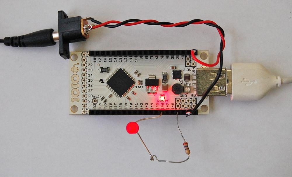
The longer lead of the LED is the positive lead. This is be inserted into the socket for pin 46 on the IOIO. Bend out the other lead of the LED and twist it together with one lead of the resistor. Push the unconnected lead of the resistor into one of the GND sockets, as shown in Figure 1-11.
All that remains is to reconnect our phone to our computer so that we can change the LED pin to 46.
Open the file MainActivity.java in Eclipse and change the line:
led_ = ioio_.openDigitalOutput(0, true);
to read:
led_ = ioio_.openDigitalOutput(46, true);
Redeploy the application to your phone and then plug your phone into the powered up IOIO. You should now be able to turn the external LED on and off.
Conclusion
In the projects that follow, we will use the IOIO in various different ways. We will make use of digital and analog inputs and outputs to build a series of projects.
Take some time to select a project that you would like to build, order the parts and then have some fun making it. Photographs, videos, source code, and pre-built apps for the project can all be found at the website for the book.
Get Making Android Accessories with IOIO now with the O’Reilly learning platform.
O’Reilly members experience books, live events, courses curated by job role, and more from O’Reilly and nearly 200 top publishers.
