2.22. STATE-VARIABLE DIAGRAM
The state-variable diagram provides a physical picture that is useful in understanding the state-variable concept. In addition, the differential equations relating the state variables are easily obtained by inspection of the diagram. A state-variable diagram consists of integrators, summing devices, and amplifiers. Outputs from the integrators denote the state variables. It should be noted that the state-variable diagram is the same as an analog computer simulation diagram [15].
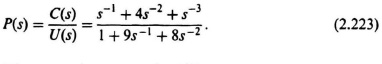
Example 1. As an example of determining the state-variable diagram, consider a system whose transfer function is given by
![]()
Dividing numerator and denominator by s3, to obtain the result in terms of integrators:
Defining the error node of the control system to be E(s),
![]()
Eq. (2.223) may be rewritten as follows:
![]()
From Eq. (2.225) and the relation
![]()
the state-variable diagram can easily be obtained as indicated in Figure 2.30*. The state variables are indicated in the diagrams as x1(t), ...
Get Modern Control System Theory and Design, 2nd Edition now with the O’Reilly learning platform.
O’Reilly members experience books, live events, courses curated by job role, and more from O’Reilly and nearly 200 top publishers.

