PROBLEMS
3.1. (a) For the mechanical translational system illustrated in Figure P3.1, write the differential equation relating the position y(t) and the applied force f(t).
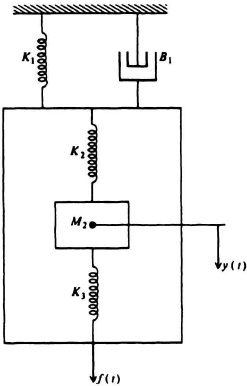
Figure P3.1
(b) Determine the transfer function Y(s)/F(s).
(c) Determine the phase-variable canonical vector form of this system.
3.2. (a) For the mechanical translational system illustrated in Figure P3.2, write the differential equation relating the position y(t) and the applied force f(t).
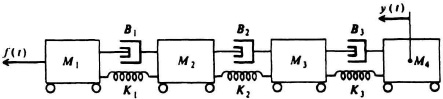
Figure P3.2
(b) Determine the transfer function Y(s)/F(s).
(c) Determine the phase-variable canonical vector form of this system.
3.3. (a) For the mechanical rotational system illustrated in Figure P3.3, write the differential equation relating T(t) and θ(t).
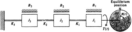
Figure P3.3
(b) Determine the transfer function θ(s)/T(s).
3.4. Figure P3.4 represents the diagram of a gyroscope which is used quite frequently in autopilots, stabilized fire control systems, and so on. Assume that the rotor speed is constant, that the total developed torque about the output axis is given by
![]()
where K′ is a constant, and that the inner gimbal’s moment ...
Get Modern Control System Theory and Design, 2nd Edition now with the O’Reilly learning platform.
O’Reilly members experience books, live events, courses curated by job role, and more from O’Reilly and nearly 200 top publishers.

