4.4. STATE-VARIABLE SIGNAL-FLOW GRAPH OF A SECOND-ORDER SYSTEM
In the previous section, the derivation of the time response of the second-order system was based on the transfer-function derivation. Therefore, an implicit assumption was made that the initial conditions were zero. This section illustrates how the state-variable signal-flow graph method of the underdamped case yields a more versatile and complete solution in the time domain including the response to the initial condition terms.
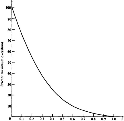
Figure 4.5 Percent maximum overshoot versus damping ratio for a second-order system.
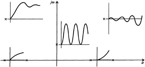
Figure 4.6 Responses of a second-order control system for various root locations in the s-plane (conjugate roots are not shown).
The state-variable signal-flow graph for this system can be derived from Eq. (4.3) as follows:
![]()
Dividing through by s2, we obtain
![]()
Defining
![]()
we may rewrite Eq. (4.34) as
![]()
From Eq. (4.36) ...
Get Modern Control System Theory and Design, 2nd Edition now with the O’Reilly learning platform.
O’Reilly members experience books, live events, courses curated by job role, and more from O’Reilly and nearly 200 top publishers.

