PROBLEMS
5.1. Assume that the system shown in Figure P5.1 has the following characteristics:
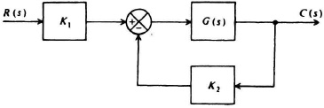
Figure P5.1
K1 = 10 V/rad,K2 = 10 V/rad,G(s) = ![]()
(a) Determine the sensitivity of the system’s transfer function H(s) with respect to the input transducer, K1.
(b) Determine the sensitivity of the system’s transfer function H(s) with respect to the feedback transducer, K2.
(c) Determine the sensitivity of the system’s transfer function H(s) with respect to G(s)
(d) Indicate qualitatively the frequency dependency of ![]()
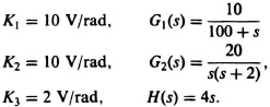
5.2. For the system in Figure P5.2, assume the following characteristics:
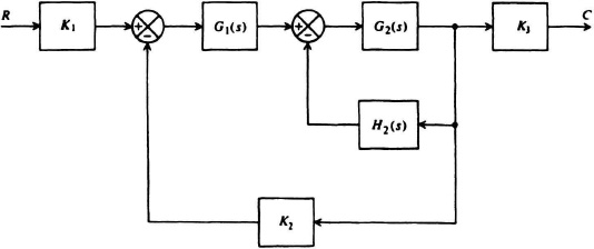
Figure P5.2
(a) Determine the sensitivity of the system’s transfer function H(s) with respect to G1(s) at ω = 1 rad/sec.
(b) Determine the sensitivity of the system’s transfer function H(s) with respect to G2(s) at ω = 1 rad/sec.
(c) Determine the sensitivity of the system’s transfer function H(s) with respect to H2(s) at ω = 1 rad/sec.
(d) Determine the sensitivity of the system’s transfer function
Get Modern Control System Theory and Design, 2nd Edition now with the O’Reilly learning platform.
O’Reilly members experience books, live events, courses curated by job role, and more from O’Reilly and nearly 200 top publishers.

