7.2. CASCADE-COMPENSATION TECHNIQUES
Let us consider the system of Figure 7.1 as our basic starting point in order to analyze the effect of cascade compensation. The compensating transfer function Gc(s) is designed in order to provide additional phase lag, phase lead, or a combination of both at certain frequencies, in order to achieve certain specifications regarding stability and accuracy. We will illustrate and derive the transfer functions for representative compensating passive networks [1–6].
A phase-lag network is a device that shifts the phase of the control signal in order that the phase of the output lags the phase of the input over a certain range of frequencies. An electrical network performing this function was illustrated in Table 2.4 as item 4. Its transfer function was
![]()
This can be written in the following more useful form:
![]()
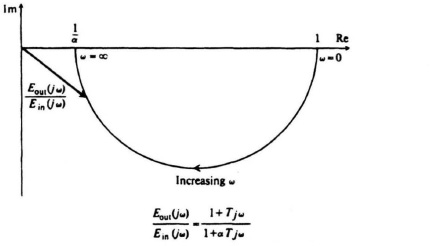
Figure 7.8 A complex-plane plot for a phase-lag network.
where
T = R2C2, α = 1 + R1/R2.
Observe that αT > T. A complex-plane plot of this network as a function of frequency is shown in Figure 7.8. Notice that the output voltage lags the input in phase angle for all positive frequencies. In addition, observe that the magnitude of Eout(jω)/Ein ...
Get Modern Control System Theory and Design, 2nd Edition now with the O’Reilly learning platform.
O’Reilly members experience books, live events, courses curated by job role, and more from O’Reilly and nearly 200 top publishers.

