PROBLEMS
7.1. Determine the circuit structure, the values of resistance and capitance, the gains of any amplifiers required, and the complex-plane plot for first-order networks having the following characteristics:
(a) Phase lead of 60° at ω = 4 rad/sec, a minimum input impedance of 50,000 Ω, and an attentuation of 10 dB at dc.
(b) Phase lag of 60° at ω = 4 rad/sec, a minimum input impedance of 50,000 Ω, and a high-frequency attenuation of 10 dB.
(c) A phase-lag-lead network having an attenuation of 10 dB for a frequency range of ω = 1 to ω = 10 rad/sec and an input impedance of 50,000 Ω.
In all cases, limit the maximum values of resistance to 1 MΩ and capitance to 10 μF. Furthermore, assume that the loads on the networks have essentially infinite impedance.
7.2. The system illustrated in Figure P7.2 consists of a unity-feedback loop containing a minor-rate-feedback loop.
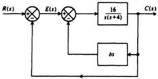
Figure P7.2
(a) Without any rate feedback (b = 0), determine the damping ratio, undamped natural frequency, peak overshoot of the system to a unit step input, and the steady-state error resulting from a unit ramp input.
(b) Determine the rate-feedback constant b which will increase the equivalent damping ratio of the system to 0.8.
(c) With rate feedback and a damping ratio of 0.8, determine the maximum percent overshoot of the system to a unit step input and the steady-state error resulting from a unit ramp ...
Get Modern Control System Theory and Design, 2nd Edition now with the O’Reilly learning platform.
O’Reilly members experience books, live events, courses curated by job role, and more from O’Reilly and nearly 200 top publishers.

