PROBLEMS
8.1. The control system illustrated in Figure P8.1(i) contains linear-state-variable-feedback elements h1 and h2.
(a) Determine the gain K and the linear-state-variable-feedback constants h1 and h2 so that the resulting control system represents a zero steady-state step error system and its characteristic equation contains roots at −2 + j, −2 − j, and −8.
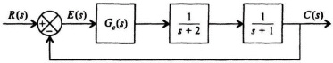
Figure P8.1(i)
(b) The same performance can be obtained as in part (a) if we implement a series controller, Gc(s), instead of using linear-state-variable-feedback as illustrated in the configuration shown in Figure P8.1(ii).
Figure P8.1(ii)
Determine the transfer function of Gc(s) in terms of K, h1, and h2 obtained in part (a) and the other system parameters provided.
8.2. A control system containing a controller and a process are illustrated in the block diagram in Figure P8.2(i).
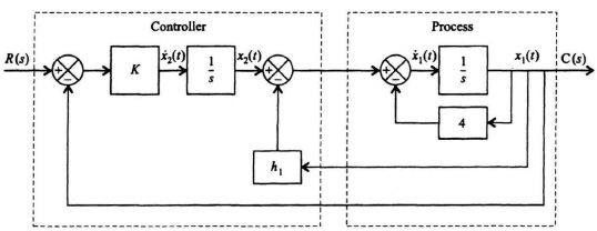
Figure P8.2(i)
(a) Determine the state equations of this control system.
(b) Determine the characteristic equation from knowledge of P.
(c) Determine the constant h1 and the gain K if the roots of the characteristic equation are at −6 and −8.
(d) Instead of using the controller configuration, the control-system engineer wishes to design ...
Get Modern Control System Theory and Design, 2nd Edition now with the O’Reilly learning platform.
O’Reilly members experience books, live events, courses curated by job role, and more from O’Reilly and nearly 200 top publishers.

