Virtual LANs, or VLANs, are virtual separations within a switch that provide distinct logical LANs that each behave as if they were configured on a separate physical switch. Before the introduction of VLANs, one switch could serve only one LAN. VLANs enabled a single switch to serve multiple LANs. Assuming no vulnerabilities exist in the switchâs operating system, there should be no way for a frame that originates on one VLAN to make its way to another.
Note
When I wrote the first edition of Network Warrior, I had not yet learned of VLAN-hopping exploits. There are ways to circumvent the VLAN barrier. Attacks such as switch spoofing and double tagging are methods used to gain access to one VLAN from another. Though reading data from another VLAN is not so easy, denial-of-service attacks could be accomplished through VLAN hopping, especially where trunks interconnect switches. Donât rely on VLANs as your sole means of security, especially in high-risk environments.
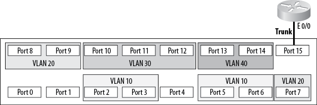
Figure 4-1 shows a switch with multiple VLANs. The VLANs have been numbered 10, 20, 30, and 40. In general, VLANs can be named or numbered; Ciscoâs implementation uses numbers to identify VLANs by default. The default VLAN is numbered 1. If you plug a number of devices into a switch without assigning its ports to specific VLANs, all the devices will reside in VLAN 1.
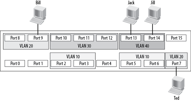
Frames cannot leave the VLANs from which they originate. This means that in the example configuration, Jack can communicate with Jill, and Bill can communicate with Ted, but Bill and Ted cannot communicate with Jack or Jill in any way.
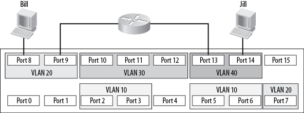
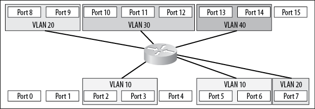
For a packet on a Layer-2 switch to cross from one VLAN to another, an outside router must be attached to each of the VLANs to be routed. Figure 4-2 shows an external router connecting VLAN 20 with VLAN 40. Assuming a proper configuration on the router, Bill will now be able to communicate with Jill, but neither workstation will show any indication that they reside on the same physical switch.
When expanding a network using VLANs, you face the same limitations. If you connect another switch to a port that is configured for VLAN 20, the new switch will be able to forward frames only to or from VLAN 20. If you wanted to connect two switches, each containing four VLANs, you would need four links between the switches: one for each VLAN. A solution to this problem is to deploy trunks between switches. Trunks are links that carry frames for more than one VLAN.
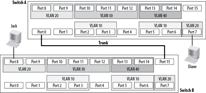
Figure 4-3 shows two switches connected with a trunk. Jack is connected to VLAN 20 on Switch B, and Diane is connected to VLAN 20 on Switch A. Because there is a trunk connecting these two switches together, assuming the trunk is allowed to carry traffic for all configured VLANs, Jack will be able to communicate with Diane. Notice that the ports to which the trunk is connected are not assigned VLANs. These ports are trunk ports and, as such, do not belong to a single VLAN.
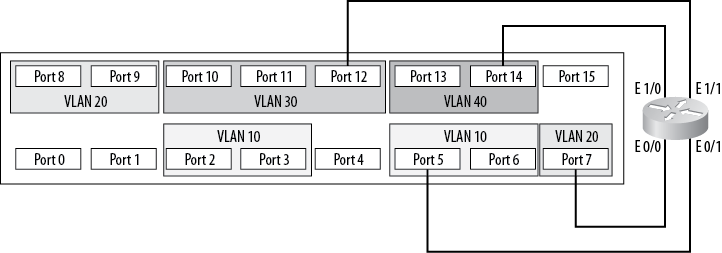
Trunks also allow another possibility with switches. Figure 4-2 shows how two VLANs can be connected with a router, as if the VLANs were separate physical networks. Imagine you want to route between all of the VLANs on the switch. How would you go about implementing such a design? Traditionally, the answer would be to provide a single connection from the router to each network to be routed. On this switch, each network is a VLAN, so youâd need a physical connection between the router and each VLAN.
As you can see in Figure 4-4, with this setup, four interfaces are being used both on the switch and on the router. Smaller routers rarely have four Ethernet interfaces, though, and Ethernet interfaces on routers can be costly. Additionally, users buy switches with a certain port density in mind. In this configuration, a quarter of the entire switch has been used up just for routing between VLANs.
Another way to route between VLANs is commonly known as the router-on-a-stick configuration. Instead of running a link from each VLAN to a router interface, you can run a single trunk from the switch to the router. All the VLANs will then pass over a single link, as shown in Figure 4-5.
Deploying a router on a stick saves a lot of interfaces on both the switch and the router. The downside is that the trunk is only one link, and the total bandwidth available on that link is only 10 Mbps. In contrast, when each VLAN has its own link, each VLAN has 10 Mbps to itself. Also, donât forget that the router is passing traffic between VLANs, so chances are each frame will be seen twice on the same linkâonce to get to the router, and once to get back to the destination VLAN.
Note
When I edited this chapter for the second edition, I briefly contemplated updating all the drawings to bring them more in line with currently common interface speeds. I decided against it because the last time I saw anyone doing router on a stick, the fastest switches only had 10M interfaces. It had nothing to do with me being too lazy to change the drawings.
To be painfully accurate, running a trunk to a firewall and having
the firewall perform default gateway functions for multiple VLANs
employs the same principle, so you could argue that Iâm just too lazy
after all. I would then counter with the fact that the latest switching
technology from Cisco, the Nexus line, has done away with interface
names that describe their speed, and instead names all Ethernet
interfaces as âe slot/portâ. Therefore, Iâm
not lazy, but rather forward-thinking.
Then I started writing the VoIP chapter where, lo and behold, I configured router on a stick in order to get my Voice-VLAN trunked to the router. Good thing I didnât pull the router-on-a-stick section. It looks like I was being forward-thinking after all.
Figure 4-6 shows conceptually how the same design would be accomplished with a Layer-3 switch. Because the switch contains the router, no external links are required. With a Layer-3 switch, every port can be dedicated to devices or trunks to other switches.
Get Network Warrior, 2nd Edition now with the O’Reilly learning platform.
O’Reilly members experience books, live events, courses curated by job role, and more from O’Reilly and nearly 200 top publishers.

