Note 32. Designing FIR Filters: Background and Options
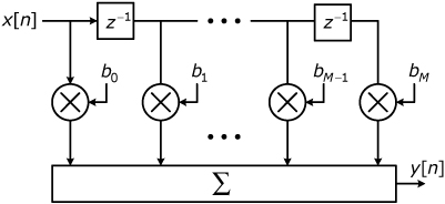
The block diagram in Figure 32.1 represents the canonical form for an Mth order finite-impulse response (FIR) digital filter in that the diagram is a direct implementation of the filter’s defining difference equation:
32.1
![]()
Figure 32.1. Block diagram for FIR filter

Examination of the equation reveals that the filter’s output at time n is simply a weighted sum of the inputs at times n – M through n. The notation used in Eq. (32.1) is consistent with the notation used in the difference equation ...
Get Notes on Digital Signal Processing: Practical Recipes for Design, Analysis and Implementation now with the O’Reilly learning platform.
O’Reilly members experience books, live events, courses curated by job role, and more from O’Reilly and nearly 200 top publishers.

