4.2 DIRECT DETECTION RECEIVER MODEL
The photodetector output current is processed by the general block diagram shown in Figure 4.6. The detector is loaded by the output impedance RL, producing a voltage signal that can be filtered or amplified for signal processing. The impedance RL can be a separate load resistance or can represent the input impedance of the postdetection circuitry. Often the resistance RL is in parallel with any shunt capacitance that also may be present in the detector loading. The linear filter–amplifier is assumed to have a filter function with bandwidth wide enough to cover the modulation process m(t) and an arbitrary voltage gain G. The effect of any postdetection filtering on this modulation can be determined by straightforward circuit analysis.
The photocurrent output will have added to it the detector dark current, the latter having the shot noise spectrum in Eq. (3.8.13),
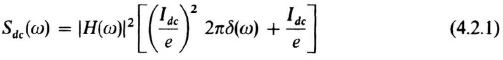
Note that the dark current also contributes a constant dc current (Idc), with random, white shot noise added to it. Hence the dark current shot noise level will add directly to the detector noise level in Figure 4.5.
To the detector output, we add in the thermal noise current caused by the local resistance RL that combines with the detector current. Thermal noise has the two-sided spectral level
in amps2/hertz, where To is the load-resistor temperature in Kelvin, and κ is again Boltzmann's ...
Get Optical Communications, 2nd Edition now with the O’Reilly learning platform.
O’Reilly members experience books, live events, courses curated by job role, and more from O’Reilly and nearly 200 top publishers.

