“The world is a jungle in general, and the networking game contributes many animals.”
The operation of an IPv4 network requires the use of several different kinds of addresses at different layers of the networking model, but also the resolution of these addresses to one another. This chapter describes the address resolution process, gives real-world examples of the messaging used, and provides insight into potential security risks associated with its use.
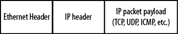
A vast majority of IP packet-based data transmission begins and ends on a LAN. This is true regardless of whether the IP packet is going to a neighbor on the same LAN or to the other side of the world. Chapter 3 describes how IP packets are encapsulated in LAN frames that use Layer-2 MAC addressing for both the source and the destination nodes. The source MAC address is easy to determine. The problem is the determination of the destination MAC address.
With Ethernet as a LAN infrastructure, a frame is constructed using the sender’s own address as the source at Layer 2 and IP address as the source at Layer 3. The destination IP address (or at least the name) is usually known, leaving only the determination of the destination MAC address. Figure 4-1 is a packet-capture review of these addresses shown in an encapsulated ICMP message.

This is an example of a transmitted frame where the source and destination MAC addresses has been previously determined.
Methods for the determination of the destination MAC address include closed-form computation, table lookup, and message exchange. Some of these options are listed in RFC 894, which describes Ethernet encapsulation.
Closed-form computation calculates the unknown MAC address from the known IP address. The sending node fills in the destination MAC in the Ethernet frame from the calculated value. This method is very quick and does not require outside resources or communication. It also allows reasonably tight control over the address space. However, it does require configurable MAC addresses and some level of management, as the addresses must all be assigned to the various hosts.
Table lookup provides each host with a list of MAC addresses and the corresponding IP addresses. This is also very fast, as the sender needs to consult the table only before building the Ethernet frame. Replacing even a single network card mandates that all tables be updated.
These methods have an advantage in terms of speed, but impose heavy management oversight. Individual host addresses must be configured and the hosts will have to be notified of any changes. For this reason, networks today (with the exception of some WAN connections) rely on the distributed approach or message exchange using the address resolution protocol, or ARP. Message exchange does add extra traffic to the network and is slower than the other methods. However, this message exchange technique is totally automated and therefore very attractive.
ARP is built into the IP configuration of every node. This means that developers at Microsoft, Sun, Google, and in the open source community develop their operating systems for operation on an IPv4 network, and code for ARP is included.
The nice thing about ARP is that for basic operation, there are only two messages defined: an ARP request and an ARP reply. When a host must find the MAC address of the destination, it will send out an ARP request. This is after the node consults its ARP table and determines that the address is in fact unknown.
Upon receipt of the ARP request message, the destination will send back an ARP reply. Basically, the ARP request asks, “Can I have your MAC address?” and the reply says, “Sure, here it is.” Hosts never say no if they can help it. Figure 4-2 shows this message exchange.

Wireshark interprets this conversation as a question followed by an answer. In the first line, one node (192.168.1.1) is asking about 192.168.1.254 and in the response, 192.168.1.254 gives its location as 00:19:55:35:1a:d0, which is a MAC address.
The construction of the two ARP messages types is shown in Figure 4-3 and later in Figure 4-5. Consider the details of the two message types, paying special attention to the addressing used in both the frame and the ARP fields.
The ARP message format is straightforward and consists of the following fields:
- Hardware type
The type of MAC address being sought
- Protocol type
The Layer-3 protocol in use
- Hardware size
The length of the MAC address
- Protocol size
The length of the protocol address
- OpCode
The type of ARP message
- Sender MAC address
The MAC address of the machine sending the request
- Sender IP address
The protocol address of the machine sending the ARP request
- Target MAC address
The MAC address being sought
- Target IP address
The protocol address of the destination
The terms hardware address and protocol address are used as general descriptions, but operationally these will almost always be Ethernet six-byte hardware addresses and IP four-byte addresses. The OpCode will be either a request or a reply.
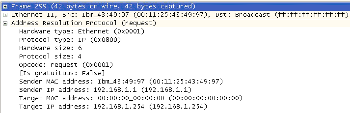
Three of the four addresses in an ARP request packet are known: the source and destination IP and the source MAC. This leaves only the destination MAC unknown. The request packet is completed by padding the unknown address field with 0s. The reply will fill in the correct value.
Line 2 of Figure 4-3 shows that the Ethernet frame source MAC is the machine sending the request, but the frame destination MAC is a broadcast address. This ensures all nodes pay attention, thereby guaranteeing that if the destination is connected and powered up, it will respond.
While there are IP or protocol addresses used in this message, it does not actually have an IP header. The IP addresses seen are simply part of the ARP header. This means that ARP messages are not routable and that routers will not pass ARP traffic on to another network. Consequently, the MAC address of a node not on the source node’s LAN cannot be determined.
It also means that the Ethertype in an Ethernet frame carrying an ARP message is different than standard data traffic. This difference is shown in Figure 4-4.
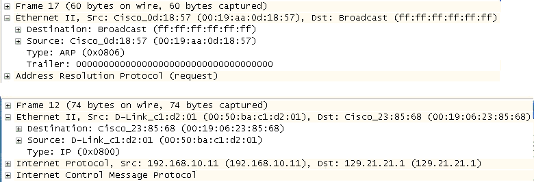
Frame 17 in Figure 4-4 has a hexadecimal type value of 0x0806 and lacks an IP header. Frame 12 has a hexadecimal type value of 0x0800 and does have an IP header. This difference can affect packet filtering or the firewall rules in place depending on the information sought.
The ARP reply depicted in Figure 4-5 is the response to the request sent in Figure 4-3, with the missing MAC address filled in. The reply is heading in the opposite direction. Thus, the sender and target addresses are now reversed. The code field has also changed to a reply.
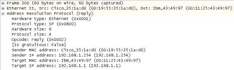
In the Ethernet frame itself, instead of a broadcast destination, both MAC addresses are now unicast. The reply goes directly to the original sender from the target and other nodes will ignore the frame.
Upon receiving this message, the original source host will do two things:
Build the data frame using the newly determined MAC address information in the destination field.
Populate the local ARP table.
Step 1 satisfies the original goal of sending a message to the destination. The second step populates an ARP table to save time during the next transmission to the same destination. The ARP table is a collection of recently learned MAC addresses and corresponding IP addresses. The next time the host must transmit a frame, it will search for the address in local memory and use the addresses found there instead of issuing more ARP requests. An example of an ARP table is shown in Figure 4-6.
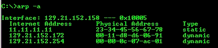
This output was obtained on a Windows machine with the command
arp -a issued from the command shell.
Notice the two types of entries—static and dynamic. The normal entry will
be a dynamic entry. Static entries are uncommon.
The dynamic nature of these entries indicates that they are not permanent. Regardless of the underlying operating system, all nodes will age out ARP table entries in a matter of minutes. Windows, for example, removes these entries after approximately two minutes. If a node is to be addressed, but has been aged out of the ARP table, the ARP process must be repeated for that node.
The time that an ARP table entry should be allowed to live has been debated, as there are differing opinions as to the perfect time. If the value is too short, the hosts will be reARPing at an increased rate and generating more network traffic. If the time is too long, bad or erroneous information may stick around longer and prevent hosts from reaching the proper destination.
With an understanding of what takes place under the hood, two examples will help illustrate ARP packet formation for near and far destinations when ARP table information is nonexistent.
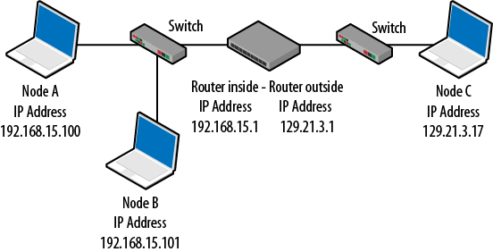
A common troubleshooting technique is to ping a target IP as “proof of life.” Ping generates an ICMP echo request packet that is encapsulated in an IP packet, which, in turn, is encapsulated in an Ethernet frame, as shown in Figure 4-7.
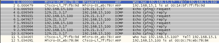
Packet capture activity of the frame depicted in Figure 4-7 is shown in Figure 4-8.
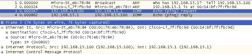
The MAC address requested in frame 1 is returned in frame 2. It is then used in frame 3 to build the Ethernet frame carrying the ping (ICMP echo), with Node A attempting to contact the router on its LAN (Figure 4-9). While the example here uses ping with the associated ICMP echo request/reply messages, the same ARP request and reply would have been required had the sender issued a Telnet, FTP, or HTTP request to the target.
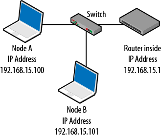
As with our first example, when the sender and target are on separate LANs, the Ethernet frame’s destination MAC address must be determined. In this case, the destination node is on a remote LAN. Since Layer-2 MAC addressing is restricted to the local network, assistance is required from the designated default gateway that will route the frame to the destination network. Router ARP behavior is similar to that of hosts. They respond to ARP messages and have to locate locally connected nodes.
To accomplish this, the sending node determines the gateway’s MAC address and places it in the destination field, as shown in Figure 4-10. As before, frame 3 is expanded to show that in the ICMP echo request, the router MAC address is used.
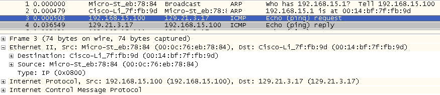
To summarize, the sender is attempting to determine the target MAC address, but the ICMP echo request is heading for a destination on another network. So the ICMP echo request uses the default gateway MAC address (00:14:bf:7f:fb:9d), but the IP address is for the distant node. Shown in Figure 4-11, Node A is now trying to contact Node C.
The question to ask at this point is, “How did the original source node know that it had to replace the MAC address of the destination host with the MAC address of the router?” Hosts first process their own routing tables to determine if the host is on the same LAN. Then the ARP process takes over. The algorithm the hosts use is discussed in Chapter 7.
The standard operation of ARP is pretty simple: broadcast a message requesting the MAC address for a particular IP address and receive an answer. However, there are a couple of key “helper” tasks accomplished by ARP that either add a little security or improve performance of the network.
The conversation shown in Figure 4-12 illustrates another important facet of ARP—only the host originating the conversation (generating the ARP request) will place an entry for the destination host in its local ARP table. That is, other stations hearing the exchange, even if they are receiving the ARP request, will not add these stations to their own ARP tables. However, many hosts (especially routers) are aggressive when it comes to populating their tables and, upon hearing ARP traffic or being involved in ARP messages, will subsequently generate their own ARP requests to populate their tables.
The packet capture sequence shown in Figure 4-12 shows the original host using ARP to determine its default gateway when attempting to send to an offsite host. After the conversation has been routed, the router (default gateway) issues its own ARP request for the original (sending) host. In this way, it populates its table with what it believes is a valid host address. This improves routing efficiency for future traffic forwarding.
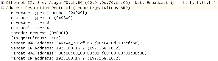
When a host boots up, it either receives an IP address via DHCP or has one statically configured. But the host must make sure no other network node is using the same address. For this reason, network hosts will often ARP for themselves. If a device answers, the sender is alerted that another node is using the same IP address. Figure 4-13 shows the target IP address and sender with gratuitous ARP.
The distributed approach to address resolution can be subject to attackers. Although hosts should only populate their tables with information they have requested, not all operating systems are programmed this way. Some older systems will allow unsolicited ARP traffic to fill a host’s cache, accepting an ARP response even if it was not requested. This allows attackers to populate the ARP table with bogus data, resulting in hosts forwarding traffic based on erroneous information.
An attacker can also take advantage of a device’s desire to populate its ARP table by providing an answer for every address on the network. In this way, it claims to have a valid MAC address for all hosts on the network, so hosts and routers on the network will believe that the attacker address is to be used for all destinations. The effect is that the valid network hosts send their traffic to the attacker, who then makes copies of the data and sends the traffic on to the correct destination.
This is called a man-in-the-middle attack because the attacker has placed herself between the proper source and destination and is effectively invisible. The technique of inserting bad data into unsuspecting host ARP tables is called ARP poisoning.
You can diagnose this type of attack by examining the ARP tables on the host machines and the routers, looking for multiple entries with identical MAC address. Security heuristics will also look for excessive ARP messages on the network. While these tables are easy to access, overworked network administrators do have to look, so this information is often missed.
ARP is absent in IPv6. Rather, networks hosts use a series of messages called redirects, solicitations, and advertisements in a process called neighbor discovery. Instead of using an approach that requires hosts to discover MAC addresses when they are needed, IPv6 adopts a slightly different process. Neighbor solicitation and advertisement messages help discover information about the network before it is needed. These messages are multicast out to all IPv6 nodes. Examples of these packets are given in Chapter 6.
ARP, a distributed approach to address resolution and discovery, is not without problems. Consider the traffic generated in a 100-node network where each host must discover every address on the network. If nodes do not cache information as a result of a transmission from a neighbor, every node has the potential to send 99 messages. Adding another 99 messages for the corresponding replies brings the total to 198 for that single requesting node. For n nodes, each node will generate 2(n−1) messages or a total of n * 2(n−1) packets or 2n(n−1).
Half of the 2n(n−1) messages, n(n−1), are broadcast frames traveling throughout the entire Layer-2 network (wired and wireless) and all of them are necessary, but are considered overhead because they do not carry user data. It is unlikely that most of these frames will be generated at the same time, but there are times (for example, at the beginning and end of the work day) when a large number of network hosts will be transmitting concurrently. Complicating matters is the fact that ARP tables age out for nodes that are not routinely participating in message exchanges. Refreshing those tables further adds to network traffic.
Routers are burdened with the additional problem of resolving the addresses next hop routers. Thus, when a router receives a message to be sent to a distant host, it must first determine the MAC address of the neighboring router. At the other end, the router receiving an IP packet may have to ARP for the destination host, further adding delays to the message traffic. As a result, it is not uncommon for the first packet of a transmission to be delayed or lost while addresses are being resolved. For this reason, routers will aggressively populate their ARP tables with known hosts.
IPv6 alleviates some of this, but creates other traffic issues, as the discovery process uses several different types of message, some of which are multicast. Switch behavior with multicast is similar in that multicast frames are sent everywhere throughout the Layer-2 domain. While routers, switches, and hosts have some ability to filter multicast traffic, we have increased the number of message types (redirects, router advertisements, router solicitations, neighbor advertisements, and neighbor solicitations), arguably increasing the overhead on the network.
This chapter has taken you through the operation and structure of ARP. This information will be about all you will need to handle ARP on almost any network. However, there are some operations or standards that you should familiarize yourself with, even though you are not likely to run into them very often. Some of these are listed below.
- RFC 826: “Ethernet Address Resolution Protocol”
This is the base address resolution standard. While not very descriptive, current operation is based on this RFC.
- RFC903: “A Reverse Address Resolution Protocol”
This RFC approaches the issue of address resolution from the opposite direction. Instead of trying to learn a MAC address, RFC 903 describes how a host can discover a protocol (IP) address if it knows only the MAC address of the destination.
- RFC1293: “Inverse Address Resolution Protocol”
This RFC allows a host to request a particular protocol address for a given hardware address.
- RFC 1868: “ARP Extension — UNARP (Proxy ARP)”
This RFC suggests some solutions for potential limits of the original ARP RFC.
In this chapter, we examined the problem of Layer-2 address resolution. After examining the packets themselves and the addressing used, you should now have a solid understanding of ARP. We have also examined several of the operations used and the security threat represented by this distributed approach.
How many addresses are defined in ARP?
Is an ARP message routable?
Describe the Ethernet addressing used in the standard ARP request. Are the source and destination addresses unicast, broadcast, or multicast?
Describe the Ethernet addressing used in the standard ARP reply. Are the source and destination addresses unicast, broadcast, or multicast?
What is a gratuitous ARP?
What information is stored in an ARP table?
Can we send standard ARP messages directly to computers that are not on our own network?
Is ARP included in IPv6?
Is ARP a secure protocol?
What is the Ethertype hexadecimal value for an ARP message?
2
No, the messages do not contain an IP header.
The ARP request uses a unicast address for the source and a broadcast address for the destination.
The ARP request uses a unicast address for the source and a unicast address for the destination.
This is a node sending an ARP request out for its own IP address in order to determine if another node is using the same address.
The ARP table contains a mapping between host MAC and IP addresses. It also shows whether each entry is static or dynamic.
No, ARP is not routable.
No
No. False ARP messages can be created to fool ARP tables. Hosts then make incorrect forwarding decisions. ARP transmissions are also sent in the clear.
0806
Materials: A Windows computer with a network connection
In Windows, click the Start button.
In the run box, type
cmdand press Enter. A command window opens.Type
ipconfig /all. This will display the IP address of your computer. The output will be similar to the following. This shows your IP address and the address of the default gateway.Windows IP Configuration Mini-PCI Express Adapter Physical Address. . . . . . . . . : 00-22-68-90-D5-DB DHCP Enabled. . . . . . . . . . . : Yes Autoconfiguration Enabled . . . . : Yes IPv4 Address. . . . . . . . . . . : 192.168.15.100(Preferred) Subnet Mask . . . . . . . . . . . : 255.255.255.0 Default Gateway . . . . . . . . . : 192.168.15.1 DHCP Server . . . . . . . . . . . : 192.168.15.1 DNS Servers . . . . . . . . . . . : 24.56.123.4 106.12.34.56 NetBIOS over Tcpip. . . . . . . . : Enabled
Materials: A Windows computer with a network connection
In the command window, type
arp -a. This will provide the same output shown in Figure 4-6. This gives an idea about nodes on the network with whom the computer has recently communicated.Record the IP addresses you see in this table, as you’ll need them later.
Materials: A Windows computer with a network connection and packet capture software
To capture the ARP traffic, first clear the ARP table or cache. To do this, type
arp -d
          *
in the command window, then typearp -ato verify there are no entries.In Wireshark, select your adapter and start a capture.
Back in the command window, ping one of the nodes previously listed in the ARP table. In the capture window, you should see the ARP request and ARP reply. These will be followed by the ICMP traffic. In pinging the default gateway, you may see the return ARP. That is, after pinging the gateway and seeing the associated traffic, the gateway generates its own ARP request directed back to you.
Materials: A Windows computer with a network connection, packet capture software, and a DHCP server like a Linksys router
To see a node ARPing for itself, typically the best time is right after an exchange with the DHCP server. This can be done on startup or by forcing the node to go through the IP address release and renewal process.
Start another capture.
In the command window type
ipconfig
          /release
. This forces the node to give up its IP address.In the command window type
ipconfig
          /renew
. This causes the node to ask for an IP address again.After the DHCP exchange has completed, you should see your node ARP for the very IP address it was assigned during the exchange. This is the gratuitous ARP.
Materials: A Windows computer with a network connection
In the command window, type
arp
          -a
to show the other nodes on the network.Ping one of these nodes to refresh the ARP table entry.
At an interval of about 30 seconds, repeat the command
arp -auntil the entry disappears from the ARP table. How long did it take?
Get Packet Guide to Core Network Protocols now with the O’Reilly learning platform.
O’Reilly members experience books, live events, courses curated by job role, and more from O’Reilly and nearly 200 top publishers.

