Enter the expansion of Voice over IP with its disruptive transition of voice from the old circuit switched networks to new IP-based networks
Several years ago, most of the writing about Voice over IP (VoIP) was about how important it was going to be, what protocols were going to dominate, the need for higher education to adopt VoIP course work, and the impact on the industry. VoIP and its companion, Unified Communications, are now here to stay. The decision facing most companies is not if they will deploy VoIP but when. There is a need for graduates of communication programs and network professionals to have an in-depth understanding of IP-based voice topologies and protocols. If you read the introductory portion of this book, then you know it offers a comprehensive look into the architecture and standards used in VoIP deployments. For those not intimately familiar with the concepts and issues associated with this increasingly ubiquitous technology, I present this chapter.
This first look into VoIP will cover most of the issues associated with typical deployment and is designed to give you enough information to have an intelligent conversation. As you read, you will discover that VoIP represents a complete change to the methods used to communicate. This chapter starts with a quote regarding the open source product Asterisk and its start into VoIP. I would argue that the term “disruptive” may have been too soft. VoIP represents a complete change to almost everything in the communications pathway. About the only thing that stays the same is the size and shape of the desktop phone. Most folks involved with VoIP would agree that these are very positive changes—especially for consumers. Businesses also benefit from reduced infrastructure and personnel costs. Modern companies are expected to run VoIP on some portion of the network. Those in industry also point out that even traditional telephony providers use VoIP technologies behind the scenes.
VoIP is also known by terms such as Internet Telephony, Computer Telephony, and even Windows Telephony. Attempts to define VoIP involve explaining how it is essentially running telephone calls over the Internet—like Vonage or Skype. All you need is a high-speed Internet connection and an adapter. But if you are actively working with the protocols or researching what is best for your company, you know that there is a lot more to it. You may also know that a successful transition often entails battling things like interoperability and having to analyze packet captures.
A little reflection recalls a time when Internet Service Providers (ISPs) transitioned to high-speed options such as digital subscriber lines and cable. But your telephone was still provided by the traditional local exchange carrier. With the greater capacity for data connections, someone got the idea that it might be possible to run a telephone call over an Internet Protocol (IP) based network. Our friends at Digium were one of the first to point out that traditional providers would never have moved to improve services or offerings were it not for the open-source community and the VoIP protocols.
Some of the first attempts included point-to-point connections or websites working as the centralized call server. Calls like these were plagued by quality issues and a complete lack of industry support. But the idea was out. And what an idea it was—free telephone calls over the Internet? Sign me up! It was a golden dream for some (consumers) and a nightmare for others; namely, the providers. After all, telephone companies made a lot of money without a whole lot of competition. It wasn’t long before services such as Vonage, Skype, and Time Warner voice made their appearance. Some of these services offered calling plans for less than half the price of traditional carriers. Some of them, most notably Skype, had as one of their goals putting telephone companies out of business. Even though price plans have settled out somewhat, wars continue with companies like majicJack and Ooma. The perceived quality can vary quite a bit, but there is no doubt that the monopoly held by traditional telephone companies has been broken and that industry is seeking employees possessing knowledge of VoIP in their skill sets.
This chapter will provide the background necessary to answer fundamental questions about VoIP and provide insight into the operations common to most VoIP deployments. Let’s begin with a definition of VoIP, explaining why it became so popular and discussing the issues associated with this growing technology.
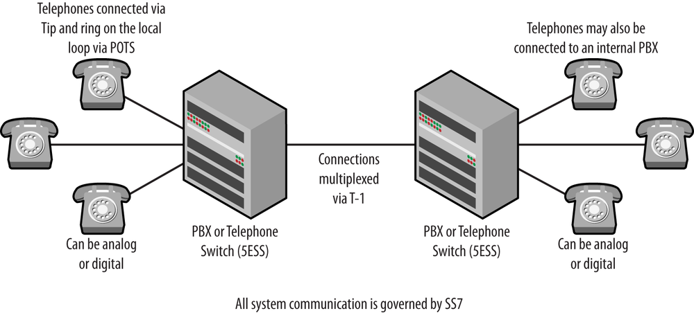
To start, VoIP is exactly what the name indicates—sending voice (and video) over an IP-based network. This is completely different than the circuit-switched public telephone network that I grew up with. Circuit switching allocates resources to each individual call. Traditional telephony services are usually described by terms such as Signaling System 7, T carriers, plain old telephone service (POTS), the public switched telephone network (PSTN), tip and ring connections, dial up, local loops, circuit switching, and anything coming from the International Telecommunications Union. All of these refer to a system that has been used for decades to deliver reliable, low-bandwidth telephone calls with a high level of quality. A simple traditional topology might look like the one shown in Figure 1-1. This traditional operation will be covered in greater detail in Chapter 2.
IP networks are packet switched, and each packet sent is semi-autonomous, has its own IP header, and is forwarded separately by routers. Chapters 3 through 7 will take us through the technical details regarding the operation of a VoIP system, but it turns out that understanding VoIP and its impetus is often a matter of understanding the effects of VoIP, which can be significant.
Native VoIP systems do away with much of what is considered traditional telephony. Well, almost. A system like the one pictured in Figure 1-1 involves a lot of control signaling to accomplish the various tasks required. For example, telephone numbers are dialed, and those numbers have meaning. Sounds or tones such as busy and off-hook are also messages of a sort. Database lookups for 411 or 800 numbers require additional messages as do services like caller-id, advanced features, and call routing. These signals are sent between the devices like the private branch exchange (PBX) before any human communication can occur.
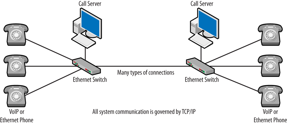
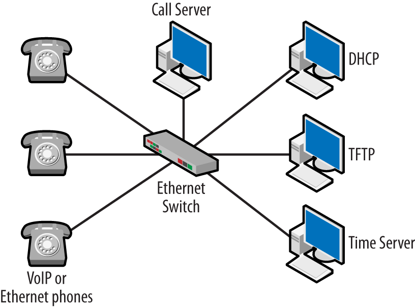
VoIP takes all of these signaling messages and places them inside IP packets. While traditional telephones can be used in conjunction with a VoIP system, it is often the case that they are not. After a pilot project, companies implementing a VoIP system commonly desire to roll out a single set of equipment in order to simplify support and maintenance. This also reduces cost. After this occurs, endpoints are not referred to as telephones anymore, just VoIP or Ethernet phones. The PBX name is retained, although it is now called an IP PBX, which really means it is a server running on a computer. Redrawing the topology, we might see something like the one shown in Figure 1-2. It is also worth mentioning that since the Internet Protocol can and does run over almost every single type of low-layer communication architecture, Voice over IP can as well.
And this indicates just how big an understatement a simple definition of VoIP can be. The languages spoken by the two systems are completely different, with traditional systems using Signaling System 7 (SS7) and VoIP networks using Transmission Control Protocol/Internet Protocol or TCP/IP. This also explains why the Digium folks call VoIP disruptive. Everything about this system is different.
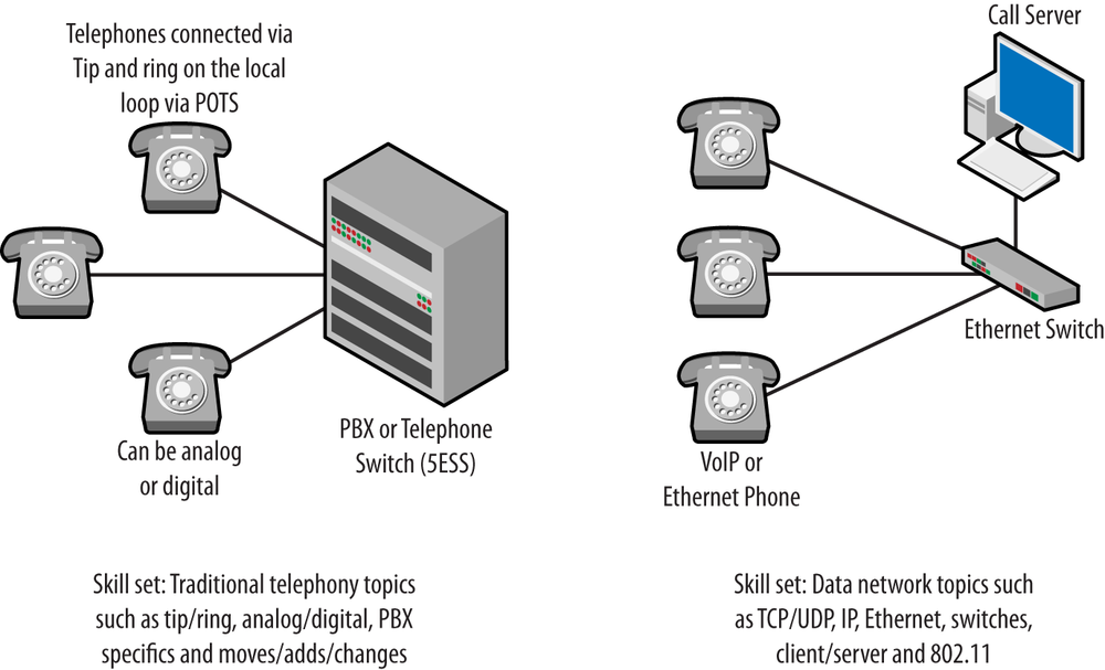
To finish this section, let’s take a quick look at the skill sets required to run the two systems. Figure 1-3 shows a side-by-side comparison of the topologies and a short list of the basic skills required to work on each. At first glance, the topologies do not seem all that different, especially as they are drawn. But, the equipment used in each, while serving the same functions, performs these functions differently and in fact operates using a completely different set of protocols.
A Venn diagram comparing the skills for each topology would find very little intersection. Following this line of thought to the hiring or training activities in an organization, we have to conclude that there would be a different demand for someone knowledgeable in traditional telephony topics compared to someone possessing a data network background. When faced with the need to support a VoIP infrastructure, what would the two individuals have to learn? If we consider the typical deployment on the consumer side, the traditional telephony person may possess knowledge about dial plans, call routing, T-1s, and features but will not understand the operation of an IP-based wired/wireless network.
A person possessing a data network background (Ethernet, 802.11, IP, TCP, UDP) would find that VoIP has migrated to the area of their expertise. They would be missing knowledge about the operation of a telephony system. However, many of the telephony skills would not be necessary. For example, moves or adds and changes are simply a matter of moving the phone and obtaining a new IP address. The debate over which individual would have an easier time transitioning has points on both sides, but there is no question that each side is missing something. This is somewhat mitigated by the proliferation of IP-based voice and location services, such as those offered by Google. It seems that we are all becoming a bit VoIP-ish whether we know it or not. Disruptive indeed.
When you are downloading a file, delays are inconvenient and sometimes vexing, but they do not damage or prevent the transfer. Similarly, when visiting a website, if the page loads slowly, we are willing to give it a few seconds before navigating away. If some of the images from the page appear, we may be willing to wait even longer. These examples constitute transfers involving nonreal-time data. From a protocol standpoint, the transmission control protocol (TCP) is used to manage the connection, and all packets (or at least the bytes) are controlled via the associated sequence numbers. Lost or delayed data is retransmitted in order to ensure that the receiver has everything.
Figure 1-4 depicts a TCP packet with the sequence numbers circled. The two endpoints in the connection communicate not only the data sent (sequence numbers) but also, with the acknowledgment number, indicate the next chunk of data expected.
Even though the bytes sent are closely monitored via the sequence numbers, the time it takes to receive them is not. So, packets may be delayed or even early. The important idea is that the user and the system are somewhat forgiving of delay, at least until the delay becomes so great the packet is considered lost. With TCP, the connection is strictly controlled and will not proceed without a complete set of packets. Most applications based on TCP are not real-time. From a user perspective, delays in applications are annoying but not prohibitive. We complain but we wait.
Real-time data is just the opposite. Real-time generally refers to something that is time sensitive. Delay that might have been acceptable for nonreal-time data can degrade performance and user experience to the point where the service or connection is unusable. Voice is a perfect example. Imagine a telephone conversation in which each participant must wait a second or two before receiving answers to statements or questions. We can see examples of this when watching a news broadcast in which the reporter is overseas. If, in the same conversation, the system were to lose a word here and there, the conversation becomes even more difficult. However, unlike the file transfer, we do not want the lost word returned. The connection would experience further delay waiting for the missing packet (packet loss), or it could be reinserted into the conversation in the wrong place. Lastly, if the packets arrived at a rate that varied (jitter), it might lead to unpredictable performance. Thus, the desire is to keep latency, packet loss, and jitter to much lower values on real-time data connections. From a protocol standpoint, the user datagram protocol (UDP) is usually deployed because we do not want retransmissions or the return of lost data. UDP does not keep track of sequence or acknowledgment values.
Figure 1-5 provides an example of a UDP packet. Besides the port numbers, the header does not include any information that might be significant for the connection. In fact, UDP is sometimes considered a fire-and-forget protocol because once the packet leaves the sender, we think nothing more about it. If the packet is lost, no response is required. Many real-time applications such as games and videos use UDP because the developers do not want to concern themselves with lost or delayed packets. Performance of the application might suffer if they did. The packet in Figure 1-5 also happens to encapsulate a Real-Time Transport Protocol (RTP) message. RTP is used by VoIP deployments to transfer voice and video data.
With all of this disruption, why would we switch to Voice over IP? Probably the biggest reason for adopting a VoIP-based architecture is money. Instead of paying for a series of telephone lines or circuits, customers need only pay for a data connection. This is because the VoIP traffic travels in IP packets that can share the data connection. In addition, IP packets can flow to any destination connected to the Internet, and toll charges are much reduced. There are several business cases in which forklift (removing everything in favor of the new equipment) changes to telephony infrastructure are justified based on the savings in toll charges alone. VoIP architectures can pay for themselves in a relatively short period of time, giving the company a good Return on Investment, or ROI.
There are several other, less obvious, opportunities to save money with an IP-based VoIP solution. Networks deploying VoIP are often called converged networks because they share the data network. Once the data network is installed, all other devices are connected to it. This actually extends to other systems such as heating and cooling systems, security, and video cameras. The impact of this change is hard to overestimate:
Single network to support
Single set of devices
Single set of maintenance requirements
Single set of employee skills
Many “off the shelf” components
Single cable infrastructure
Easier moves/adds/changes
All of these lead to a lower total cost of ownership, or TCO, for the network.
This is not to say that switching to VoIP eliminates specialized or expensive components. Indeed, some of the pricing structures or licensing fees for VoIP phones or PBXs are very similar to their traditional counterparts. VoIP desktop phones do not come cheap, with the more advanced models running hundreds of dollars. However, one advantage is the ability to deploy softphones instead of physical units. Softphones (phone software running on a laptop or handheld device) can be much less expensive and easier to manage.
The single set of employee skills is worth another look. VoIP systems run on the data network but are telephony systems that have been converted to IP-based protocols. The ideas and functions are the same. Companies consolidating infrastructure sometimes find themselves with a collection of employees that no longer possess the skills for the current infrastructure. As mentioned earlier, they may lack a background in the protocols and hardware associated with a data network. However, these employees are also the ones that understand the telephony side of things. On the other hand, data network administrators may have little or no knowledge of telephony. So a conversion to VoIP may require different types of training: vendor specific, basic network, and VoIP specific. Leveraging both groups of employees may provide the best possible outcome for the deployment.
And this brings us to the business case for VoIP. The justification for VoIP is often based on the Return on Investment. That is, how long will it take for the change to pay for itself? There are several situations in which VoIP has demonstrated a good ROI; these include upgrades to the current infrastructure, planned replacement of failed or out-of-date equipment, new installations, and many others.
However, there are some other, nonmonetary, benefits realized when converting to VoIP. For example, because VoIP equipment is very similar to the computers and network gear that is already deployed, the technical staff will be familiar with the issues associated with network connectivity. Thus, troubleshooting may be handled by the in-house staff. Additionally, this local expertise may reduce the mean time to repair (MTTR) and an increase in the mean time between failures (MTBF).
Employees using the VoIP endpoints may experience greater mobility if wireless phones are supported, but softphones and the ability to log into any phone may also increase mobility and productivity. Pundits often point to these advantages as well as integration with other applications as nonfinancial reasons to switch to VoIP.
Unified Communications (UC) also presents tremendous opportunities to realize improvements through integration of applications. UC systems are built upon a VoIP core, but, unlike VoIP, the case for UC is not always made through cost savings but productivity gains. The ability to collaborate, indicate presence, and use a single platform for email, messaging, and text can go a long way toward achieving these soft benefits.
However, not everyone agrees that switching to VoIP is the greatest idea. Companies that have a invested a great deal of time and money ensuring high quality of service levels, low downtime, and local expertise in their current telephony systems may not bite on VoIP for a few years yet, as the digital system provides the features and service they require.
The telephony industry is highly regulated. What is on your bill, “do not call” lists, and 911 are all tightly controlled by the Federal Communications Commission. Pricing structure, number portability, and access are also controlled by these rules. But everything about the Internet and the services running on it are different, and so are the rules. For the last couple of years, there has been a continual debate regarding the regulation of the Internet. On one hand, there are those who believe that the Internet should be a free place where ideas and communications can flourish with no restrictions placed on anyone using it; for more information, look up network neutrality. On the other hand are people concerned about protection for consumers and young people. Issues with privacy and website willingness to share or sell your information seem to call for greater regulation and more stringent laws. Of course there are also those concerned with money. If everyone were to move to free telephony, what would happen to the cost model used by so many telephone companies? How would the government replace all of that tax revenue?
One look at a telephone bill reveals just how confusing this can be. In fact, one of the first documents offered on the FCC website clarifies what you might find on your bill. What it comes down to is that you pay for telephony service and the sales tax for that service. Almost everything else on the bill is also a tax or fee. At the time of this writing, the FCC does not regulate a lot of the VoIP market. In fact, as recently as June 2012, FCC Commissioner Robert M. McDowell stated:
Governments should resist the temptation to regulate unnecessarily, get out of the way of the Internet and allow it to continue to spread prosperity and freedom across the globe. Internet connectivity, especially through mobile devices, is improving the human condition like no other innovation in world history.
A couple of the major exceptions include 911 service, discontinuance of service notification, number portability, support for the Law Enforcement Act of 1994, and contributions to the Universal Service Fund, or USF. The USF will show up on a voice service bill as a percentage (currently 9.85%) of the interstate and international call costs. The fund was established by the Telecom Act of 1996 and can provide assistance for locations such as schools, low income areas, the disabled, and health care facilities. Communications Assistance for Law Enforcement Act of 1994 (CALEA) requires that communication providers (including VoIP) enable law enforcement to perform lawful surveillance, including any modification to infrastructure that may be required. This may seem a bit heavy-handed, but the industry is largely responsible for setting standards and solutions. While all of this regulation or potential regulation is white noise to a network administrator, there are a couple of things that the professional has to worry about having available, and chief among them are 911 and power.
There is a significant difference between the operation of 911 service on traditional telephony systems and 911 on a system based on IP. The basic problem is that when a phone is identified by an IP address, geographic location is not part of the equation. By contrast, a traditional telephone is tied to a circuit that is terminated at a particular location. While it is true that an IP address is limited to an ISP and that a traditional telephone can be moved, VoIP phones are considered more mobile than telephony lines.
Adding to this are problems that are a regular part of data networks: outages, network address translation, movement or replacement of nodes, and so on. All of these elements can make it more difficult to locate an endpoint in the emergency call. Power outages can also create problems, as the VoIP service runs over powered Internet devices such as home gateways and cable or digital subscriber line modems.
Lastly, there is the very real question regarding the response to an incoming 911 call. Traditional systems have established public safety answering points (PSAP) to handle the call and connect it to the closest emergency response unit. While VoIP providers are required to establish the ability to locate an individual before offering service and must provide 911 on a nonopt-out basis, the challenges associated with locating an end node create a valid concern. Thus, finding the VoIP handset or softphone making the call becomes a very practical problem for the network administrator. This is made more difficult when we add wireless to the equation. Many vendors are beginning to offer location capabilities that made help address this challenge.
Another very practical problem is adding 911 to the dial-plan. This is not particularly new to VoIP but is worth mentioning, as it does have to be addressed. When a user dials 911, they expect a certain response. But what happens if a user remembers that they dial “9” to get off-site? In this case they may actually dial “9911” and expect the emergency response.
Traditional telephony service provides power to customers from the central office. This means that the power source for telephones was completely different than the power supplied to outlets, lights, and your refrigerator. Thus, in a power outage, telephones might be the only thing still working—unless the customer uses cordless telephones, which get power from the outlet. In a VoIP solution, power outages also kill the VoIP service by shutting down the customer premises equipment (CPE). As an example, the local VoIP PBX would probably be installed in the closet with the rest of the networking gear. Desktop telephones typically get their power from the Ethernet switches via power over Ethernet (PoE), as would the wireless access points. Backup power supplies may provide power for a certain amount of time, but these are installed to provide enough time to manage a graceful shutdown of the equipment.
But with decreasing cellular costs and slow response from the traditional telcos, many customers adopted cellular phones. Charged cellular phones typically still have service in a power outage, thanks to backup power supplies for the cellular carrier equipment. Even if they have a VoIP solution, customers simply switch to cellular. Thus, the power-loss argument is not as strong. Of course, some folks never use a wireline telephone at all.
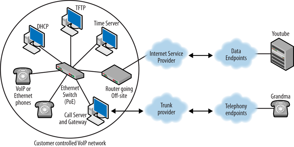
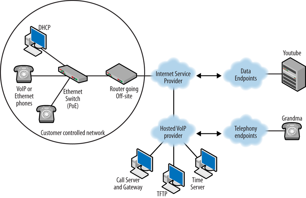
There are many topologies that can be used when constructing a VoIP solution. Each vendor has a collection of models that can be used to tailor a solution to the customer. But in a broader view, there are two general approaches: run the system yourself (on-site), or have someone else handle things, as in a hosted solution. Figure 1-6 provides an example of the first.
The left side of Figure 1-6 is the internal network, which houses the servers used to support the VoIP nodes and the VoIP phones themselves. The company is connected to the outside world via the Internet Service Provider, or ISP. Before VoIP, a company would also own a separate voice network, and these would be connected to the off-site local exchange carrier (LEC) in order to provide connectivity to the telephony endpoints. It is often the case that the ISP and LEC are one and the same. The VoIP endpoints also have to be connected to the telephony endpoints outside. Signaling traffic flows from the internal call server and gateway to the external gateway. Once again, it is possible that the ISP and VoIP gateway functions are provided by the same company. However, this is not always the case. For example, if Time Warner provides connectivity off-site via cable and gives you an IP address but your phones are managed by Vonage, the telephone signaling traffic flows through the ISP network to the VoIP carrier or trunk provider.
Companies that have a small staff or a small number of nodes or that simply do not want to run their own phone systems can opt for a hosted solution. In this scenario, very little customer premises equipment is necessary. It may be that only the desktop phones are installed within the company walls. All of the services necessary to run the phones are physically located at the provider. The provider may or may not be the ISP. This is shown in Figure 1-7.
If you decide to run your own IP PBX, there are several support components that must be part of the network. Deployment models depend on the size of the network, number of users, user requirements, and local skill level. There are also several small office home office (SOHO) solutions in which a small, low-maintenance gateway or PBX might be deployed on the customer premises. The customer may chose to administer the device or have a service contract. For even fewer headaches, the customer may opt for a full hosted solution like the one shown in Figure 1-7, and the only equipment on-site would be the phones.
Solutions scale up from there through small to medium business (SMB) models to enterprise deployments with massive integration, customer databases, and applications. Whatever the deployment model, several components must be present in order to handle several standard tasks. To start, all VoIP nodes must register with the call server. In this way, the call server understands what nodes require servicing. The call server may also be connected to several other call servers or to the outside world. Services such as directory listing or location may also be required. The following is a list of standard VoIP components; however, not all of them are required in every deployment.
- Call server
Phones register with the call server. The call server can handle security and admission control while connecting the phones. The voice data for the call, typically carried by the transport protocol, may or may not flow through the call server.
- Gateway
This device is typically used to connect an internal network to the rest of the world, or at least a different system. The system to which you are connecting may be a different technology or the same. For example, an internal network based on VoIP may connect directly to the PSTN. The PSTN is still largely controlled via SS7. The gateway will connect endpoints on either side, translate between the two systems, or provide features. On the other hand, a gateway may simply connect companies or providers together. In this case, the interconnected groups may be running the same signaling protocol.
- VoIP protocols
There are two types of VoIP protocols: signaling and transport. The signaling protocols handle all of the functions normally carried out by traditional protocols, such as the Integrated Services Digital Network (ISDN) Q.931. Standardized signaling protocols are described later in this chapter and given full attention elsewhere in this book. The transport protocol is used to encapsulate or carry the actual voice data, and the only protocol universally used for transport is the Real-Time Transport Protocol (RTP), which is described in Chapter 4. The voice data packets are created with a codec and then encapsulated within RTP.
- Codecs
This is short for a coder-decoder used for the purpose of converting the analog voice signal to a series of digital samples at the source and then back again at the receiver. Thus, the sending phone encodes the voice data with its codec, and the receiver decodes the voice packet with its codec. Codecs are present in both traditional and VoIP deployments. For a traditional system, the codec can be physically located in the phone or in the PBX, depending on the type and model deployed. VoIP phones always contain the codec. Codecs can also compress the voice data. While there are many different codecs, probably the most common audio codecs are from the ITU-T G series. The ITU-T H series contains the popular video codecs. Within the audio and video categories, codecs accomplish encoding and compression in different ways, though many are based on similar principles. Chapter 5 provides much greater detail on codecs, but a short list of these two collections would include:
G.711—Pulse Code Modulation
G.722 and G.723—Low bit-rate encoding
G.726—Adaptive Differential Pulse Code Modulation
G.729.1—Code Excited Linear Prediction variable bit-rate coder
H.261—Early video codec for p x 64 Kbps
H.263—Video coding for low bit-rate communication
H.264—Advanced video coding for generic audiovisual services
iSAC (Internet Speech Audio Codec)—a non-ITU-T audio codec developed by Global IP Solutions, used by Google Talk
- Desktop phones and softphones
The phones (also known as endpoints) in a VoIP topology perform the same service that any other phone does, albeit in a different fashion. Early in the evolution of VoIP, there were attempts to get rid of the phone entirely in favor of phone applications installed on computers. However, people were used to the traditional telephone design and didn’t like the change. The application also had to compete with whatever was running on the computer at the time. Today, we have a mix of desktop VoIP phones and telephony applications, or softphones.
- Non-VoIP components
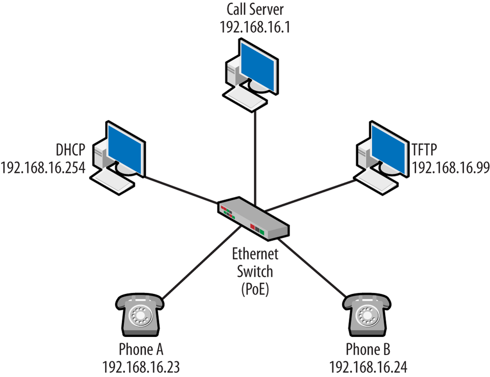
The VoIP system depends on a number of services that are not VoIP specific. Many of the services, such as the Dynamic Host Configuration Protocol (DHCP), are already part of the network architecture and can be expanded to include the VoIP components. Other services include Trivial File Transfer Protocol (TFTP), Domain Name Service (DNS), and Network Time Protocol, or NTP. It is common to see these components listed in the VoIP product requirements, as it may not run without them. A typical topology that includes these elements might look like the one shown in Figure 1-8.
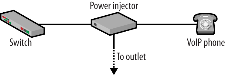
There is another non-VoIP-specific piece to this infrastructure—power over Ethernet, or PoE. Devices such as access points and VoIP phones can be powered via injectors inserted between them and the network, but these require an outlet, as shown in Figure 1-9.
This does limit the deployment of the devices, since they must be near an outlet or have one installed. This is particularly true for access points, as they are often mounted on the ceiling. Rack-mounted PoE solutions can help if the environment and distances are favorable. Moving to a VoIP can introduce hundreds of phones that need to be powered. Even if the phones are in offices, this means a lot of outlets and power to manage. PoE-enabled switches get around this by providing power directly to the phone (or access point) without needing the injector. There are three PoE methods commonly deployed, two of which are IEEE standards.
- IEEE 802.3af
Carrier Sense Multiple Access with Collision Detection (CSMA/CD) and Physical Layer Specifications, Data Terminal Equipment (DTE) Power via the Media Dependent Interface (MDI) Enhancements
- IEEE 802.3at
Amendment to 802.3af
The standard defines two ends of the connection. Power is supplied via power-sourcing equipment (PSE) side and sent to the Powered Device or PD. There are a couple of configurations regarding the electrical connections which the PSE is supposed to support. Ethernet eight-wire connections have two data pairs (1 and 2, 3 and 6), and with PoE, direct current power can be supplied on pins 4, 5, 7, and 8. This positive pair runs on conductors 4 and 5 with conductors 7 and 8 being negative. The idea is that once a device requiring power is connected to the switch, it will be detected, and only then will power be applied. Discovery is via a PD detection signature at the time of connection. The PSE actually probes the connected device for the correct electrical characteristics, as defined in the standard. This is called the physical-layer classification. Devices may also support data-link-layer classification, which uses the local area network protocol. When this is active, data-link classification takes precedence.
PSEs, the link, and the PD are considered a system that is either Type I or Type II; each type has different electrical characteristics, such as direct current limitations, resistance, and cable type. Type II carries greater current and has greater cabling requirements. The power output by the devices is a function of the supply voltage and the current draw. The PSE has the requirements of locating PDs, providing power, monitoring the power provided, and removing the power when it is not needed. This also supposes that the PSE will not provide power to a non-PoE device. Type I PDs will advertise event-class signatures of 0, 1, 2, or 3 when queried. The default is class 0. Type II is more complicated but uses class 4 and a two part selection process. Some PDs can perform mutual identification, as they may require a Type II rather than a Type I PSE. The maximum power draw is a function of the class limitations and electrical characteristics (Table 1-1).
Table 1-1. PoE specifications
| Class | Voltage | Current Min | Current Max | Min Power at output of the PSE | Average Power |
|---|---|---|---|---|---|
| 0 | 14.5-20.5v | 0 | 4mA | 15.4W | 13W |
| 1 | 14.5-20.5v | 9mA | 12mA | 4W | 3.84W |
| 2 | 14.5-20.5v | 176mA | 20mA | 7W | 6.49W |
| 3 | 14.5-20.5v | 26mA | 30mA | 15.4W | 13W |
| 4 | 14.5-20.5v | 36mA | 44mA | Defined by device | 25.5W |
The third PoE method is from Cisco. Cisco implemented PoE capability before the IEEE standards were ratified. The Cisco methodology differs from the IEEE standard in terms of negotiation, by utilizing the Cisco Discovery Protocol (CDP) and power level. Cisco also utilizes the fast link pulse to detect a connected PoE device. While Cisco devices may be IEEE compliant and support Cisco PoE, the two techniques are not compatible. Current Cisco devices support one or both of the IEEE standards.
The Cisco documentation notes an interesting problem that can crop up when a PoE device is connected and its type and class cannot be determined. The switch then allocates full power for the mystery device, though it may not be needed. The result is that power required by other devices connected to the switch cannot be supplied, thus resulting in an ersatz power-budget depletion.
Note
From a very practical side, knowledge of PoE operation is probably not necessary most of the time. An administrator might simply look up the power requirements of the connected devices in order to ensure that the switch provides the proper standard: 802.3af or 802.3at. This must also be part of purchasing decisions. Of course, troubleshooting is almost always aided by a little more domain expertise. In the example of power depletion, separating devices and understanding the signaling or potential problems can lead to quick problem resolution.
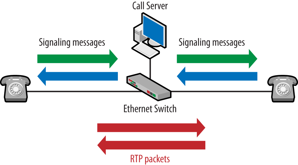
As mentioned earlier, there are several VoIP-specific protocols but only two categories: signaling and transport. The signaling protocols handle the functions derived from the telephone system architecture, and the transport protocols carry the voice packets generated from the codec. Phones use the signaling protocol to register with the call server, set up, and tear down calls. Signaling protocols are also used for features such as directory services and screen displays. Once a call has been established, the voice data packets are typically sent directly between the phones using RTP encapsulation, though there are exceptions. The flow paths are shown in Figure 1-10.
RTP packets carrying the voice data may also flow from the phone to the call server and then to the other phone.
Even though the VoIP architecture is completely different from that used by traditional telephony, we still have the basic requirement of signaling. Somehow, phones have to ring, numbers must be communicated, and routes have to be set up, and these functions are handled by the signaling protocol. The three most common types are H.323, Skinny, and the Session Initiation Protocol, or SIP.
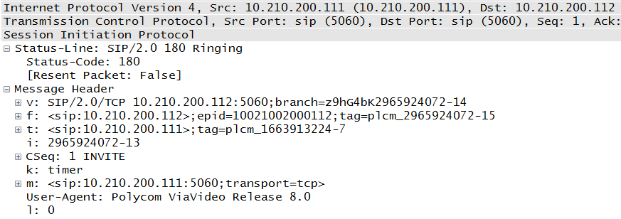
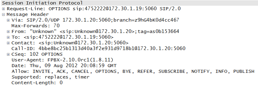
The Session Initiation Protocol (SIP) is a nonproprietary standard from the Internet Engineering Task Force, or IETF. The format of SIP messages is very close to that of Hypertext Transfer Protocol (HTTP) packets and so is very familiar to folks in the data networking world. SIP had a slow start but has largely taken over the world. Though the initial RFC was somewhat limiting, it is the signaling protocol used by most companies going forward, including Vonage and Skype. Even Cisco is transitioning from Skinny to SIP. In-depth coverage of SIP can be found in Chapter 3. A sample SIP packet can be seen in Figure 1-11.
From Figure 1-11, we can see that the packet is easy to read, it has an obvious purpose, and the parties involved are clearly defined. These characteristics and the integration with many forms of addressing are some of the reasons for the popularity of the protocol.
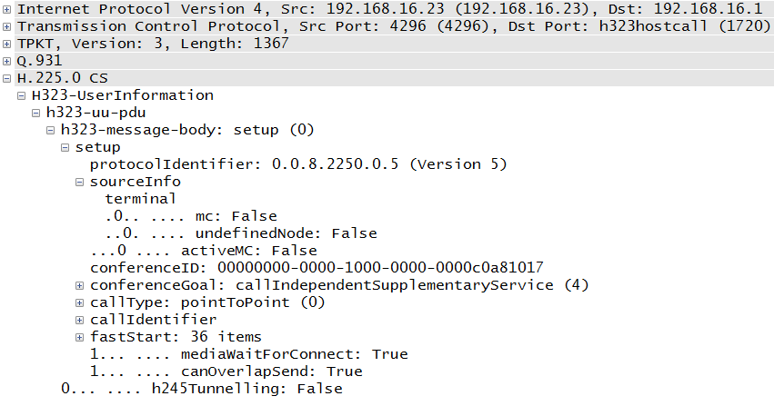
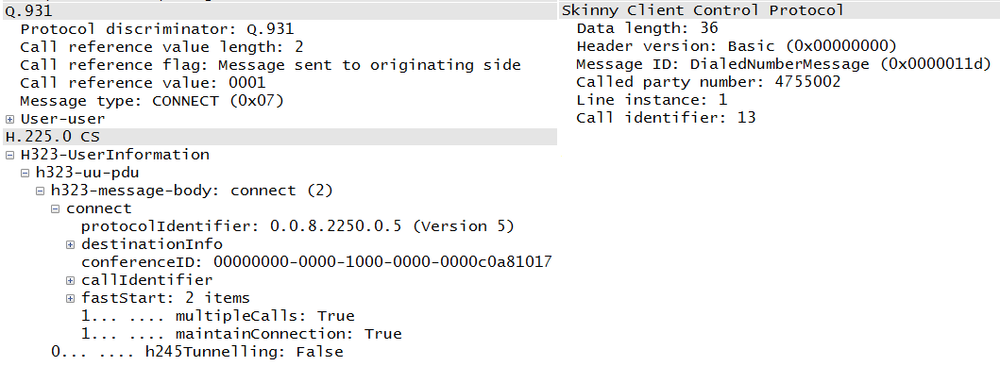
This is actually an ITU-T suite of standards that focuses on video conferencing. It was developed earlier than its competitors and thus was the de facto standard used in many deployments. It uses many of the signaling ideas from traditional telephony, and some might say that it suffers as a result of the corresponding baggage. There are several subprotocols in an H.323 session, including Q.931, H.225, and H.245. More detail about H.323 can be found in Chapter 6. A sample H.225 packet can be seen in Figure 1-12.
Examining the packet in Figure 1-12, we do not have to go very far to see the number of sublayers and fields involved. Within the TCP packet there are three sublayers (TPKT, Q.931, and H.225) before we come to the actual message information. A little further on is the “fastStart” section, which has 36 items. This complexity might be one of the reasons for its declining popularity. However, some VoIP experts point out that SIP complexity can increase depending on the endpoints and their capabilities.
The Skinny Client Control Protocol (SCCP), or Skinny, is a Cisco product. It is highly proprietary, and much of its operation differs significantly from what might be considered a normal VoIP deployment. However, Cisco has had great success with its VoIP products, and there are a significant number of Cisco networks running Skinny. Chapter 7 provides an examination of Skinny. A sample Skinny packet can be seen in Figure 1-13.
One of the nice things about the Skinny messages is that, like SIP, they are very easy to read, at least if you have an older version or recent dissectors. Most Skinny messages are short and to the point. However, Skinny is proprietary and does have some behaviors that are not seen elsewhere, such as a limited or nonexistent use of Real-Time Control Protocol (RTCP), the companion protocol to RTP.
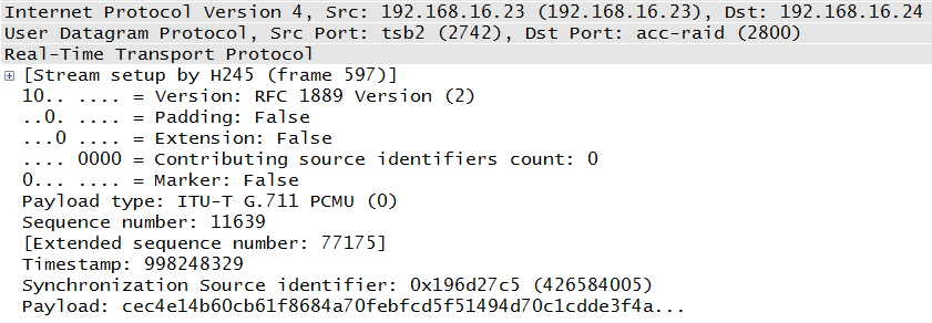
The Real-Time Transport Protocol (RTP) is the hands-down favorite for transporting voice packets containing the voice data. While there have been other mechanisms deployed, RTP is widely accepted. RTP, defined in RFC 3550, is a simple protocol that uses source IDs to collect packets from the same source, and it has a field that identifies the payload so that the receiver can determine which codec was used to create the voice packet. An RTP packet is shown in Figure 1-14.
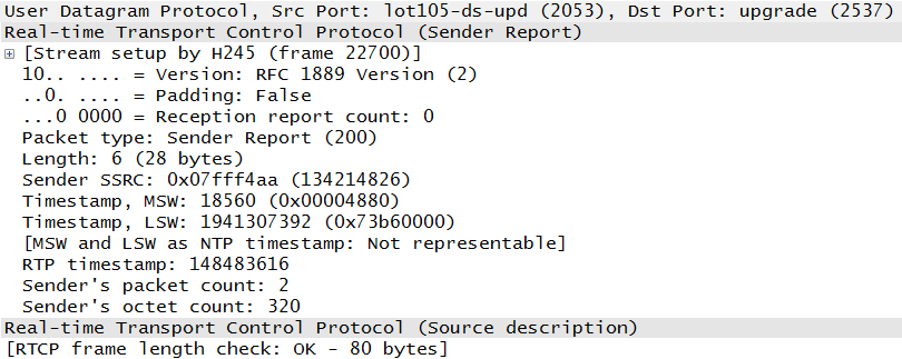
RFC 3550 also includes the Real-Time Control Protocol (RTCP), which provides information about the flow of RTP packets. Its primary use is to provide feedback on the quality of the voice stream. An RTCP packet is shown in Figure 1-15.
Comparing these packets, we can see that the RTP packet provides an indication of the codec used to create the voice packet, the source identifier, and the data itself. The RTCP packet contains none of this. Instead, RTCP keeps track of the timing and bytes sent between the endpoints. In this way, an idea of the link performance can be obtained. Chapter 4 provides greater detail regarding both RTP and RTCP.
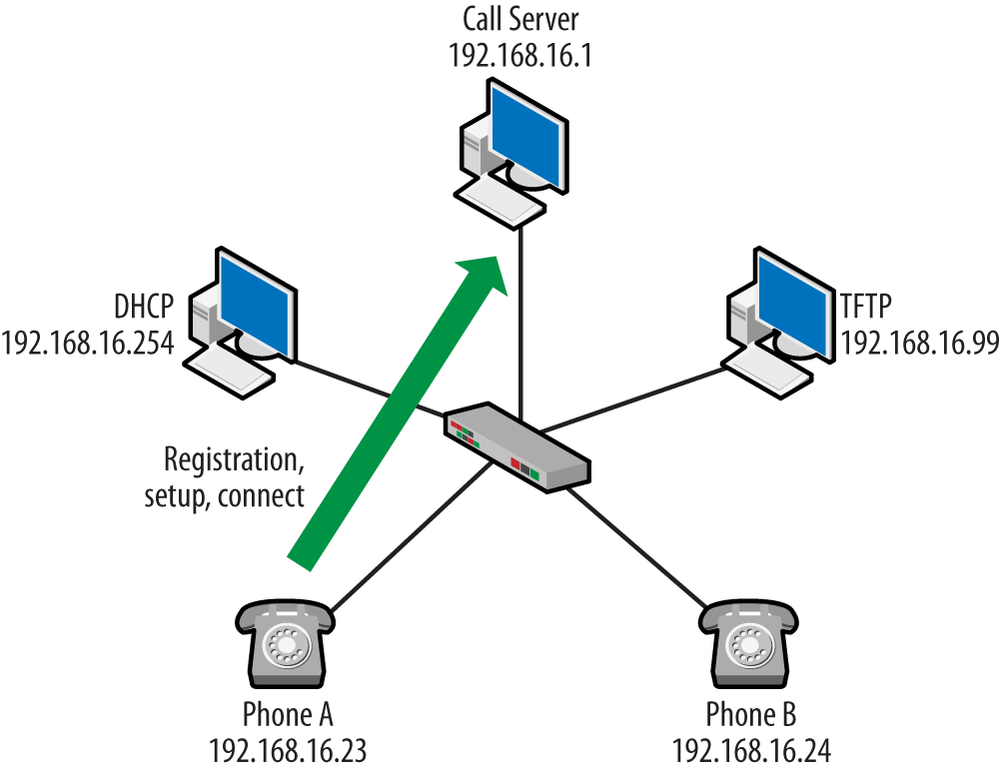
This book contains a chapter for each of the signaling protocols, and the topologies used for the explanation were built using different vendors, including Cisco, Avaya, and Asterisk. As we work through each, we will see that most VoIP deployments follow a similar template for operation and have nearly the same set of components. This section will provide the template for operation, and the chapters will provide the details specific to the topology and protocol used. For right now, the topology shown in Figure 1-16 will form the basis of our discussion.
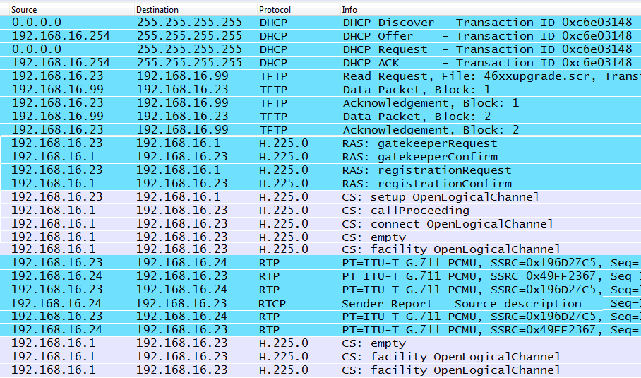
The packet list shown in Figure 1-17 depicts the packets generated as a phone starts up and then makes a call. For space, this list has been edited so that examples are shown rather than the entire conversation series. This list is from a nonproprietary H.323 connection. As can be seen, there are several parts beginning with Dynamic Host Configuration Protocol, or DHCP. After DHCP, the phone contacts a Trivial File Transfer Protocol (TFTP) server to obtain any recent updates and then moves into the VoIP-specific messaging.
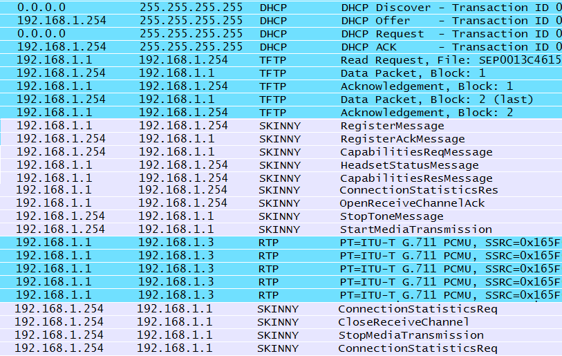
Just for fun, I’ve included another list from the proprietary Cisco architecture so that we can see both formats following a similar set of procedures. The packets shown in Figure 1-18 also progress from DHCP to TFTP and then to the VoIP-specific protocols.
- Dynamic Host Configuration Protocol (DHCP)
As we saw in the proprietary and nonproprietary packet lists, almost all VoIP deployments begin with DHCP. In addition to standard items such as an IP address and default gateway, VoIP phones require the addresses of the TFTP and call-server address. Of the two addresses, TFTP is the next step for the phones simply because there are different mechanisms used to obtain the call-server address. For example, a configuration file can be installed on the TFTP server. This file will provide values such as the call server, language, and button arrangement. Some sample Cisco DHCP configuration lines follow, and the last four lines indicate various methods for providing the address of the TFTP or call server.
ip dhcp pool voip
network 192.168.16.0 255.255.255.0
default-router 192.168.16.254
next-server 192.168.16.99
option 66 ip 192.168.16.99
option 150 ip 192.168.16.99
option 176 ascii "TFTPSRVR=192.168.16.99,
MCIPADD=192.168.16.1"
- Trivial File Transfer Protocol (TFTP)
As the name suggests, TFTP transfers are bare bones; there are no usernames, passwords, or fancy transfer types. A TFTP server is used to update the firmware used by the phone and perhaps provide a settings file that might contain operational parameters for the VoIP network. A sample from a settings file might look like this:
SET MCIPADD
          192.168.16.1
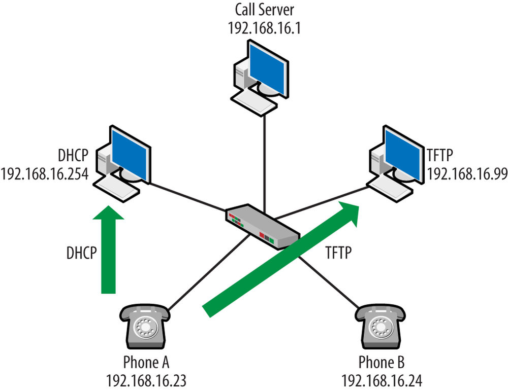
But TFTP servers are also used to provide files that describe codes or tones used in a particular region. For example, a wide variety of downloadable files might be used when configuring Cisco’s localization support. The capture shown in Figure 1-17 is from the perspective of Phone A, which receives an IP address of 192.168.16.23. Following the conversation up to this point, we can modify the topology as shown in Figure 1-19.
- Phone registration
Before a VoIP endpoint can make a call, it must first register with the call server, or gatekeeper. This process makes the call server aware of the phone and provides information for the interface on the phone. With a new installation or registration, a user will log into a phone using the phone number assigned to him or her. At this point, the IP and MAC address of the phone are now tied to that particular phone or dial number.
Registration occurs via the signaling protocol, and each signaling protocol uses a slightly different set of messages to accomplish the task. From the two conversation diagrams, we can see that H.323 uses RAS, or Registration, Admission, and Status messages, while Skinny use a registration message. In either case, it is pretty clear what is happening and that the phones perform this task before any other. Figure 1-20 depicts some variations in the register messaging.
- Phone setup
Depending on the phone model, topology configuration, and signaling protocol, there may be several H.323, Skinny, or SIP messages passed between the call server and the phone. These may be used to inform the phone of events, provide feature support, or populate the interface. Each of the signaling chapters will provide greater detail, but some of these messages can be seen in Figure 1-21 and Figure 1-22.
These messages are exchanging permitted methods (Figure 1-21) and receiving directions regarding the screen (Figure 1-22).
Both were received after the registration phase.
- Call setup and connection
In a traditional network, lifting the receiver closes a circuit in preparation for the voice signal. Users dial numbers, creating tones that are sent to the telephone switch. The switch converts the tones to digital information via the codec. The switches must establish an end-to-end circuit to the destination. None of this is packetized, meaning it is not IP-based on protocols. For VoIP, this process must now be changed from Signaling System 7 messages and telephone frequencies (such as those coming from a dual-tone multifrequency, or DTMF, endpoint) to messages encapsulated in protocols such as those outlined in this section.
The VoIP signaling protocol (H.323, Skinny, SIP) sends messages to the call server, indicating the number dialed, and the call server must contact the destination. While the protocols have different methodologies, and in fact vendors may create additional differences, these messages typically appear just before the start of the RTP stream. Figure 1-23 shows some variations on the messages starting the connection.
As we can see from the capture trace in Figure 1-18, the registration, setup, and connect messages all flow to the call server at 192.168.16.1. Updating our topology diagram, we get the result shown in Figure 1-24.
- RTP conversation
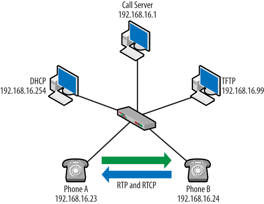
RTP is used to convey voice data. Once the RTP packets are flowing, the call has been established. However, RTP can also be used to convey samples created for other sounds. For example, a dial tone can be placed in RTP packets sent from the call server, and these packets will occur before the voice data for the call—so keep an eye on the IP addresses. The RTP packet contains a payload ID indicating the codec used. When the end user speaks into the handset, the codec takes the analog voice and creates the voice packets sent in the RTP stream. Taking a snippet from the H.323 conversation in Figure 1-17, we can see that the RTP packets are flowing between the phones. The diagram in Figure 1-16 indicates that the phones have the IP addresses of 192.168.16.23 and 192.168.16.24.
At the receiving end, the voice packets are decoded and played into the earpiece. Note that the Synchronizing Source (SSRC) values are consistent in these packets, allowing the stream to be reconstructed at either end. From the two conversations in Figure 1-17 and Figure 1-18, it can be seen that both architectures are using RTP. SIP deployments also use RTP. Another look at the RTP conversation in Figure 1-25 reveals that an RTCP packet stole in.
- RTCP
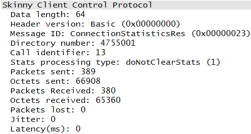
As mentioned previously and as seen in Figure 1-15, RTCP packets carry information about the RTP stream that is used to provide details about quality or performance. RFC 3550 states that RTCP will be deployed whenever RTP is used. The list of packets bears this out. However, not every deployment will obey the rules. While the lists of packets are edited, they are not edited in such as way that should mislead the reader. So, if in examining the Cisco topology, you noticed that there were no RTCP packets, your eyes are not deceiving you. Cisco uses another SCCP mechanism to accomplish the goal of RTCP, and this is shown in Figure 1-26.
If we take another look at our topology, we see that the endpoint IP addresses are communicating directly via the RTP stream, as shown in Figure 1-27. Note that all of the other devices are out of the conversation at this point.
- Call termination
In most VoIP deployments, every attempt to facilitate a graceful disconnect is made. This ensures that the channel or session is shutdown, resources are recovered, billing is determined, and no other connection data is accepted for that Call-ID. This is as opposed to simply severing the connection from one endpoint. Reviewing Figure 1-17, the signaling protocol comes back into the connection at this point and provides messages to the involved parties in order to tear down the logical circuit and recover resources. The phones are back to communicating with the call server IP address at 192.168.16.1.
With protocols such as RTCP or Skinny messages, like those shown in Figure 1-15 and Figure 1-24, paying so much attention to quality metrics for the RTP stream, one might be led to believe that VoIP performance is a big deal. Well, it is. With so many systems converting to IP, it is easy to be lulled into thinking that these are just additional applications running on the network and that the network can continue to support the additions. While some applications may survive in an increasingly busy network, voice is a very important and sensitive application. Other types of traffic (FTP, HTTP, mail, etc.) can usually weather an outage or service problem. But without voice communication, problems can get very serious for a business. If you are a network administrator, you may get some unwanted attention if voice communications fail. Thus, it is not uncommon for VoIP systems to receive additional budget consideration and personnel. We often allocate resources to ensuring that not only does the system keep running but that it has a high level of quality.
As mentioned earlier in this chapter, the three enemies to VoIP performance are latency (delay), jitter, and packet loss. Almost every object or process in the path adds latency—from the codec used, routing and switch tables in hops along the way, and the inherent behavior of the network. Jitter, or the variation in packet-arrival times, leads to unpredictable performance. Normally, jitter problems are managed with buffering. But with real-time data, the ability to provide buffering is extremely limited. Packet loss is another significant problem for any application, as retransmissions can really eat into the quality of the call. Table 1-2 provides some indication of a quality metric for calls.
Table 1-2. VoIP Quality Metrics
| Cisco | Avaya | ITU-T | |
|---|---|---|---|
| Maximum Latency (end to end) | 150msec | 80-180msec | 150msec |
| Maximum Packet Loss | Less than 1% | Target of 1%; 3% is acceptable | Less than 1% |
| Maximum Jitter | Less than 30msec | Less than 20msec | Varies based on deployment |
Though some of the values might vary a small amount, we can see that most vendors and standards are pretty close.
While this book is intended to help with the networking side of VoIP, we should at least touch on the subject of unified communications, or UC for short. UC describes what many people think of as the next step after VoIP. Many UC solutions have a VoIP core but go well beyond using the data network for audio and video. UC is perhaps best described by the problems it tries to address, namely:
Many different kinds of devices
Many different platforms
Many methods used to communicate
Many usernames, IDs, and addresses to coordinate
Unified Communications are broad attempts to collect these into a single interface or service. As a colleague of mine likes to say, “I decide what I want to send to you and how. You decide how to pick it up and in what format.” This means that a vendor offering UC services might include voice, video, email, messaging, collaborative workspace, conference, presence, and the list goes on.
It is a challenge that vendors have different definitions of UC, and they all read like a collection of buzzwords. Examples include “enhancing the quality of the interactive experience across the entire enterprise” and “the convergence of real-time and nonreal-time business communication applications.” While these definitions don’t really tell us very much, by digging a little deeper, we find that most solutions agree on a couple of key areas:
Integration with voice capabilities
Presence, both online and off-hook
Single A single user interface
Collaboration
Another piece that most agree on is that, unlike VoIP, unified communications are not sold on savings or cost improvements but on improving business processes and human productivity. Sometimes unified communications can do both, as is the case with using high-definition video conferencing instead of travel.
Voice over IP (VoIP) is quickly becoming a central component to networks, regardless of the size or type of business. System and network administrators are often asked to deploy VoIP natively or migrate traditional telephony systems to a VoIP solution. Understanding the operation of VoIP protocols and the services necessary is critical to create a successful solution. This chapter discussed a standard VoIP topology, including non-VoIP-specific components such as the Dynamic Host Configuration Protocol and the Trivial File Transfer Protocol. Signaling protocols including H.323, SIP, and SCCP were reviewed, as well as RTP, which servers use to transport voice data. Further details can be found in the chapters dedicated to these protocols. This chapter is also supported by capture files on the book’s website.
While each chapter in this book has a reading list specific to the chapter topic, this section will provide a “getting started” list. The Federal Communications Commission website has a tremendous amount of good information regarding the state of legislation and requirements for telephony service over the Internet. A good place to start is this website.
This book does not cover the justification for VoIP and Unified Communications, as that appears to have already been made. But if you would like a little more information on the business case, you can start with the Techtarget folks—and no, I didn’t get paid to say that. The work done by Digium is a great resource as well:
Asterisk—one of the documents that helped start it all: “The Future of Telephony”
RFC 3261—SIP: Session Initiation Protocol
RFC 3550—RTP: A Transport Protocol for Real-Time Applications
International Telecommunications Union–Telecom Recommendations, G and H series
What are the major signaling protocols? Which of these are proprietary?
What are the two protocols defined by RFC 3550 and their purposes?
Name three non-VoIP components used by VoIP architectures.
Describe the general order of operations for a disconnected phone that is first plugged into the network and then makes a call.
True or false: all codecs in a VoIP system reside on the call server.
Name a couple of methods by which a VoIP phone may learn about the call server.
What are the three main impairments to good voice quality on a VoIP system?
What are the target values for these impairments in order to maintain good voice quality?
True or false: the business case for VoIP and UC are made in the same way.
What are the two IEEE PoE standards?
Skinny (proprietary), SIP, and H.323.
RTP—transport of voice data, RTCP—quality and performance feedback for the RTP stream.
DHCP, TFTP, NTP.
DHCP, TFTP, registration via signaling protocol, phone configuration and call setup/connecting via signaling protocol, voice transfer via RTP, RTCP feedback, call termination and teardown via signaling protocol.
False; codecs reside in the VoIP endpoint.
DHCP, TFTP-based settings file, signaling protocol message.
Packet loss, latency, jitter.
Less than 1 percent; less than 150ms one-way; less than 30ms.
False; VoIP is sold on cost savings, while UC is sold on productivity or efficiency improvements.
802.3af, 802.3at.
This chapter is supported by the book website. So, if the activity lists equipment or software that you do not have, go to the book website for additional content.
Take a look at the reading list for this chapter. Review the standards and recommendations that were part of the discussions. Pay special attention to SIP, H.323, and RTP.
Materials: computer with web access
Explain the structure of these documents, what they contain, and where they can be found.
Discuss the basic operation of each protocol.
This activity develops reader familiarity with the VoIP protocols and topics covered in this book.
Materials: computer with web access, Wireshark
Open the capture files and examine the packets for protocol families.
Explain the basic flow of packets as they move through each of the stages.
Open packets that are specific to each of the protocols. Examine the fields contained. How much can you identify?
In addition to services such as Skype and Vonage, what are your local service offerings for VoIP?
Materials: N/A
Take a look at the Vonage and Skype sites. How is their service described? How do they handle 911 service? What are the reviews for their service? How does the cost compare with traditional landline? Cellular service?
Discover the signaling protocol that is used by your local provider or company. What are the benefits? Problems?
If you own a handheld device, does it have a voice or video app? What protocols does it use? What are the pros and cons of its performance? What can affect the performance and why?
Materials: Computer with web access.
Search the FCC website for information on the current state of regulation for VoIP.
What is the FCC position on regulating VoIP?
What is net neutrality, and how is this affected by the FCC?
The goal of this activity is to familiarize the reader with some of the tools in Wireshark and some of the performance values that are important to VoIP.
Materials: Computer with web access, Wireshark.
Open the capture files from the book website.
Using the “Telephony” menu, select RTP and “Show all streams”. At the time of this writing, Wireshark 1.8.2 was used.
Select one of the identified streams to analyze.
Can you find the packet loss, jitter, and latency values for these streams?
Do the numbers meet or improve upon the values listed in this chapter?
Do a little experimentation with the available tools—what else can you learn?
Get Packet Guide to Voice over IP now with the O’Reilly learning platform.
O’Reilly members experience books, live events, courses curated by job role, and more from O’Reilly and nearly 200 top publishers.
