Chapter 4. Tool Techniques
This chapter discusses techniques that can be used with some of the tools introduced in Chapter 3 and ties in with the discussions on fasteners found in Chapter 2. Not all of the tools from Chapter 3 are covered here in detail, because the uses for many of them are rather obvious. The objective is to expand on what was described in Chapter 3, discuss some of the little details that are often overlooked, and check out some of the less common tools.
In addition to the correct, and incorrect, use of common tools such as screwdrivers, this chapter will also cover some ways to use and modify sockets and wrenches. We’ll look at how to solder various component types, with a special focus on surface-mounted components. We’ll also cover riveting and dealing with stubborn fasteners. Drills and drill bits get a close look, along with the basics of cutting threads using taps and dies. An overview of cutting methods for dealing with sheet, bar, and rod materials is provided, which includes cut-off saws, hacksaws, the jeweler’s saw, and rotary tools. We’ll wrap up with a look at a technique for using a rotary tool that might surprise you.
This chapter is by no means a comprehensive discussion of tool usage. It is merely a summary of some useful techniques and things to look out for, along with a generous amount of advice gleaned from my own experience and the experiences of others. What works well for one person might not work well for another, and experience is the only way to develop your own techniques. This chapter is intended to be a starting point for acquiring that experience, or perhaps learning something new to add to what you already know.
Some of the tools described in this chapter can severely injure you if used incorrectly or carelessly. Always wear safety glasses when working with power tools, and always read and follow the manufacturer’s safety precautions provided with the tool. Use lubricant when working with hard metals, and never reach into a running tool of any kind to clear out metal or plastic chips. Shut the tool down first, and then clean it out. Remember that a blob of molten solder can burn a deep hole in you, and even something as seemingly innocent as a pocket knife can do some real damage.
Working with Fasteners
The fasteners described in Chapter 2 are used with a variety of tools, which were covered in Chapter 3. Choosing the correct screwdriver, hex wrench, or socket is more important than you may think. When working with any kind of fastener, you must apply a significant amount of force on the head to rotate the screw or hold it in place while threading a nut onto it. The wrong size or type of tool can slip, ruining the part. Using a socket with a small socket-head bolt or nut where the socket doesn’t seat correctly can also result in a ruined fastener.
The upshot here is that the correct tool will fit the fastener snugly, with little or no play, and it will turn or hold the fastener without damaging it. Inexpensive screwdriver and hex wrench sets are readily available that contain a selection of tools of reasonable quality, and the few dollars you’ll spend is well worth it to avoid the aggravation of not having the correct tool or needlessly damaging a fastener. Small sockets can be easily modified to seat flush on a small nut or the head of a bolt, and both box and open wrenches (also known as spanners) can be modified to fit into narrow spaces or work with low-profile bolt heads and nuts.
Screwdriver Sizes and Types
Screwdrivers, like the ones introduced in Chapter 3, come in a range of standard sizes. Table 4-1 lists commonly available screwdriver sizes for UTS/ANSI screws, for both slot and Phillips types.
| Screw gauge | Slot blade size | Phillips size |
|---|---|---|
0 |
3/32” |
0 |
1 |
1/8” |
0 |
2 |
1/8” |
1 |
3 |
5/32” |
1 |
4 |
3/16” |
1 |
5 |
3/16” |
2 |
6 |
7/32” |
2 |
8 |
1/4” |
2 |
9 |
1/4” |
2 |
10 |
5/16” |
3 |
11 |
3/8” |
3 |
12 |
3/8” |
3 |
13 |
3/8” |
3 |
14 |
3/8” |
3 |
16 |
3/8” |
3 |
18 |
3/8” |
4 |
20 |
1/2” |
4 |
24 |
1/2” |
4 |
For the #4, #6, and #8 screws commonly encountered in electronics, the #1 and #2 Phillips are the appropriate screwdriver sizes to use. A #3 Phillips is sometimes used to mount equipment in a 19-inch rack using 10–24 screws, and there are cases where a heavy component (such as a power transformer, for example) is mounted to a chassis using a 10-24 or 10-32 bolt or screw. The #4 size tools are sometimes called for when you’re dealing with things like large electrical distribution panels and automotive components, but they aren’t used much with electronic devices. Most screwdriver sets include #1, #2, and #3 sizes, and the #0 or #4 sizes can be purchased separately if they are needed.
Be careful not to confuse JIS (Japanese Industrial Standard) cross-drive screws with Phillips drive parts. There is really nothing wrong with JIS screws and JIS screwdrivers; they’re just not fully compatible with Phillips-style hardware. JIS fasteners are commonly found in electronics imported from Asia. Some tool vendors will sell imported JIS cross-drive screwdrivers as Phillips, when in reality they are actually JIS tools.
The main difference between JIS and Phillips is that a JIS screwdriver will handle a Phillips screw, but a Phillips screwdriver can wreck a JIS screw. So, if you’ve been using a JIS driver on JIS screws without realizing it, and then reach for a Phillips one day on the assumption that they are all the same, you may be in for a rude surprise in the form of a ruined JIS screw that you’ll have to drill out or cut off to remove (this is discussed in detail in “Dealing with Stubborn Fasteners”).
Figure 4-1 shows the difference between the JIS and Phillips screw heads. Note the rounded corners of the Phillips screw, whereas the JIS has sharp right angles at the intersection. Figure 4-2 shows the difference between JIS and Phillips drivers. Note that the blades on the JIS tool are slightly shorter than the Phillips one, because the slots on a JIS screw are not as deep as on a Phillips screw.

Figure 4-1. JIS versus Phillips screw heads
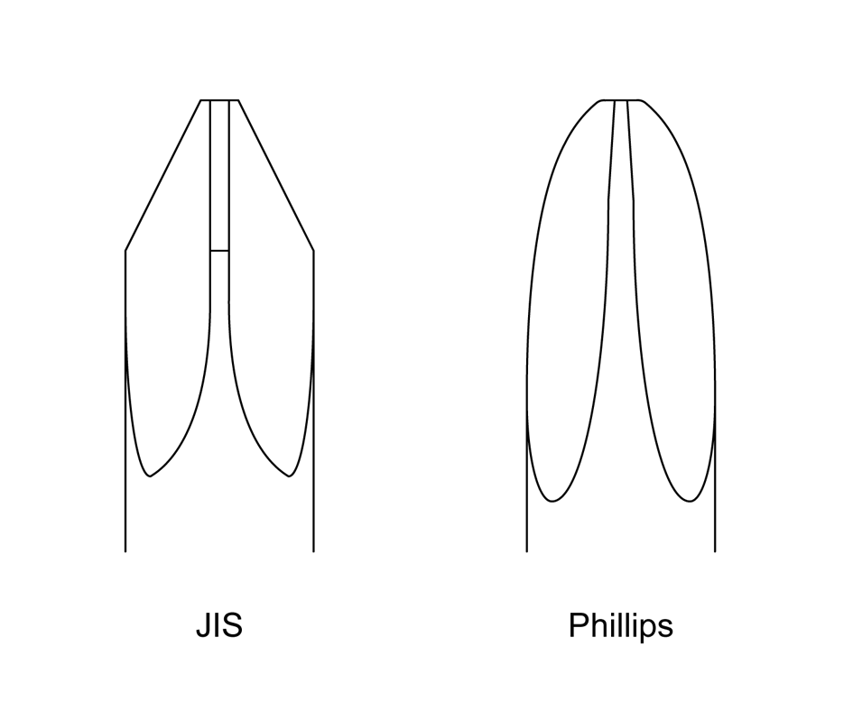
Figure 4-2. JIS versus Phillips drivers
The rounded corners at the slot intersection on the Phillips screw, along with the rounded blades on the driver, cause the tip of the screwdriver to “cam out” when the screw is fully seated and no more motion is possible. It’s an intentional design feature. The JIS tool, on the other hand, is not designed to lift out of the screw head. A Phillips screwdriver will not seat correctly in a JIS-type screw, and it might round off the corners of the slot intersection on a JIS part.
Figure 4-3 shows how to check the size and fit of a Phillips screwdriver for a given screw, in this case a 6-32. Note that the #2 screwdriver on the left fits the screw, whereas the #1 tool on the right is a little too small. It might work, but the risk of damaging the screw head is much higher.
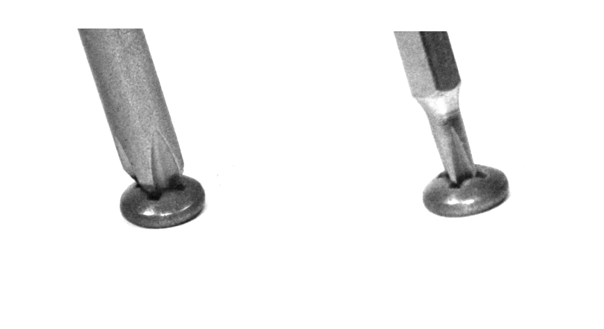
Figure 4-3. Phillips screwdriver sizing
Here’s why all of this matters: a Phillips screw with the slots twisted out of the head can be a real hassle to remove. Figure 4-4 shows a damaged Phillips screw on the right, with an undamaged part on the left for comparison. The parts are identical in terms of size and threads, but one is now completely ruined. The damage shown in Figure 4-4 can occur when a screwdriver tip is too small for the screw head, or the screwdriver was allowed to bounce in and out of the head slots after it would have normally cammed out. This is always a potential risk when you are using some type of powered driver, but not so much when you’re driving a screw by hand.
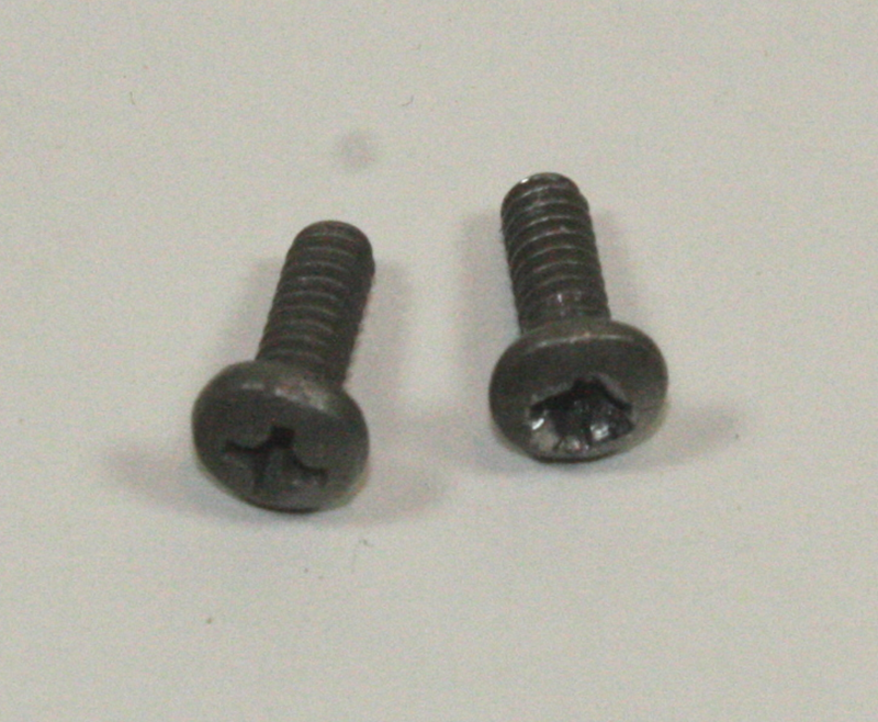
Figure 4-4. Damaged Phillips screw
Because a tool that is too large won’t fit correctly in the first place, it should be readily apparent that continuing would be a bad idea (although I have seen people try it and, as expected, end up with a ruined screw head). The importance of correct tool sizing also applies to slotted head fasteners, but as stated elsewhere, these really should be avoided if at all possible.
If you are using a power driver with screws, you should be particularly careful. I have a used Ingersoll-Rand industrial driver that I’m quite fond of, but unless the torque is set correctly, it can ruin the head of a screw in the blink of an eye. A cordless drill can also damage a screw (as anyone who has ever used one for drywall installation or woodworking can attest), and even a small hand-held driver like the one shown in Figure 4-5 can ruin the head of a screw if used carelessly.
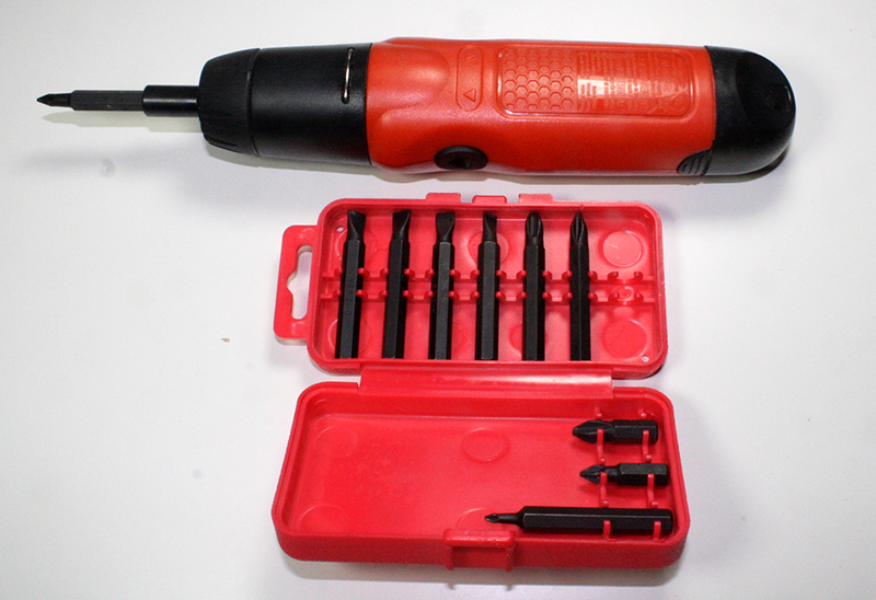
Figure 4-5. Battery-operated electric screwdriver
If used carefully, a battery-operated screwdriver like the one shown in Figure 4-5 can make your life a lot easier. If you do decide to purchase one, get a good one, preferably rechargeable. The own shown here uses AA size batteries, which occasionally will need to be replaced.
Self-Tapping Screws
Chapter 2 covered self-tapping screws, but it’s worth mentioning again that they can be problematic to work with. Once a self-tapping screw has been removed, it’s easy to drive it back in and destroy the threads it cut the first time. This is called cross-threading, and it’s generally a bad thing.
There is a trick you can try to get a self-tapping screw to line up with the threads it cut into the material when it was first installed. First, put the screw into the hole without tightening it. Then, holding it in place with a slight amount of pressure on the screwdriver, turn the screw the “wrong” way (i.e., counter clockwise), as if you were backing it out. At some point, you should feel a slight “bump” when the start of the thread is encountered (if you are working with metal, you might even hear a faint click).
Now, immediately after the bump or click, turn the screw the correct direction to tighten it (clockwise), and it should pick up the threads and go in without cross-threading. Do not apply a lot of pressure when reseating a self-tapping screw; just let the existing threads pull it in and apply only moderate pressure when it stops to tighten it.
This little trick works best with plastics and thick sheet metal. With thin sheet metal, you might not have much of anything in the way of threads to work with, but it’s still worth a shot.
Hex-Socket-Head Fasteners and Hex Wrenches
A hex wrench (also called a hex key or Allen wrench) doesn’t have a tendency to climb out of the hex socket in the way a screwdriver will with a Phillips or slotted screw. Figure 4-6 shows a hex wrench being used with a small cap-head bolt. Note that getting the wrench end fully seated in the hex socket is the secret to success.
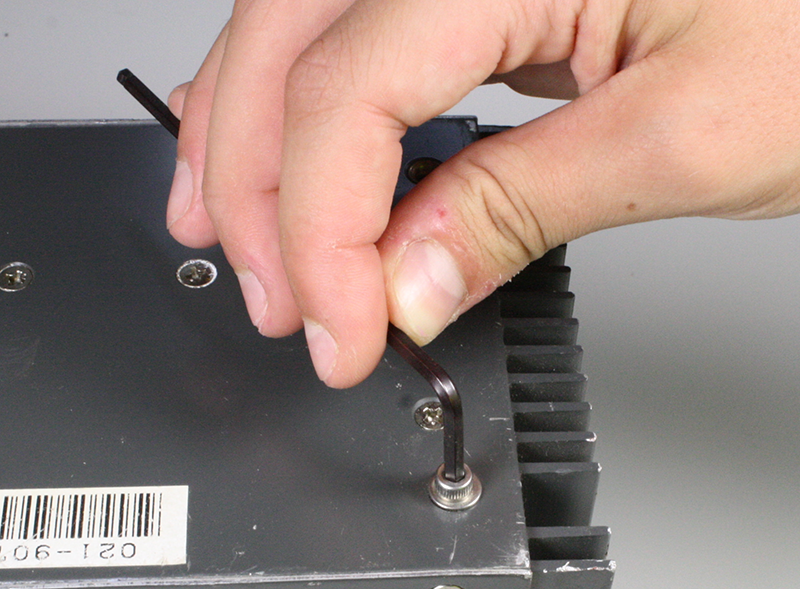
Figure 4-6. Using a hex wrench
A screwdriver is not a hex wrench, and trying to use one to tighten or loosen a fastener with a hex socket in the head will not do it any favors. Once the interior edges of the socket are damaged, a hex wrench will no longer seat correctly and the part is essentially useless. Inexpensive hex wrench sets appear often enough on the “bargain table” in hardware stores that there really isn’t a good reason not to own one.
Typically, both ends of a common hex wrench are usable, as shown in Figure 4-7. Using the “short” end allows you to apply greater torque to the fastener by applying pressure to the long arm of the tool. Inserting the long end of the wrench into the hex socket won’t allow for as much torque, but it does make it easier to spin the tool between your fingers and get the screw or bolt moving a lot faster.
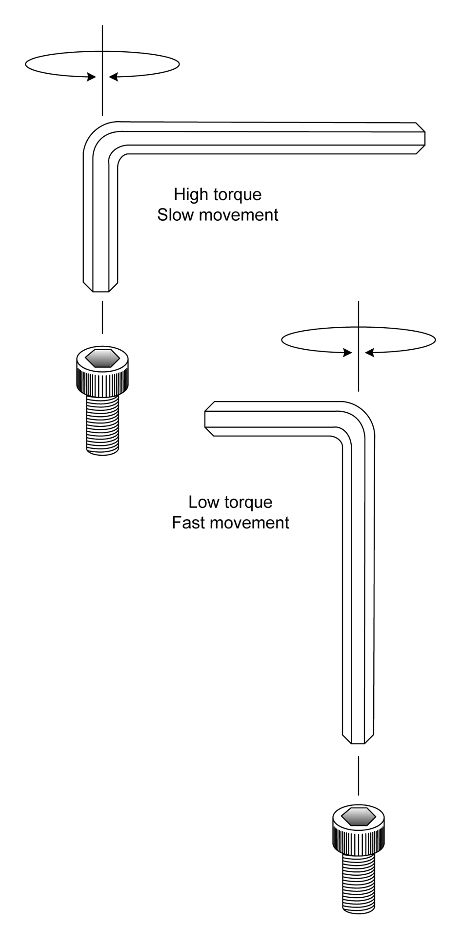
Figure 4-7. Different torque and movements possible with each end of a hex wrench
One way to take advantage of both ends of a hex wrench is to use the short end to break a fastener free and then flip the tool and use the long end to spin the fastener out. A simple concept, to be sure, but one that might not be intuitively obvious to those who haven’t worked with hex wrenches before.
If you examine different sets of hex wrenches, you might notice that some of them have flat ends, whereas others have a rounded shape like a ball. The wrench shown in Figure 4-6 is a ball-end hex wrench, and Figure 4-7 shows a flat-end type. Figure 4-8 shows a side-by-side comparison of ball- and flat-end hex wrenches.
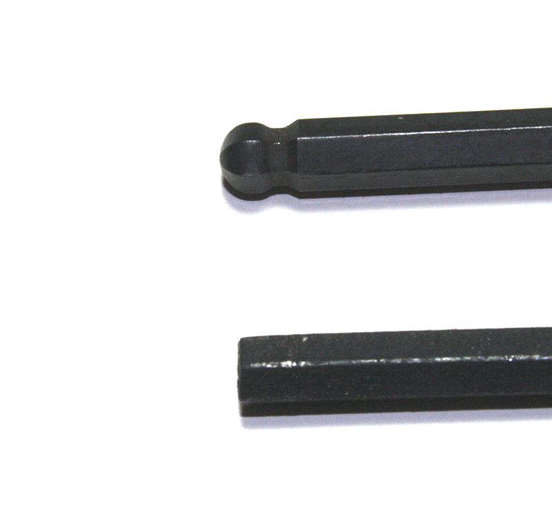
Figure 4-8. Ball-end and flat-end (straight shaft) hex wrenches
Flat-end (or straight-shaft) wrenches can tolerate higher amounts of torque and make more complete contact with the insides of the hex socket. A ball-end wrench is convenient for getting into tight spaces, but the ball doesn’t make as much physical contact with the inner walls of the socket and the narrow section (the waist) of the wrench end might break under stress. Some people like to use the flat-end wrenches to initially loosen a part and then use a ball-end wrench to turn it out. Conversely, a ball-end wrench can be used to turn a fastener into position, and then a flat end wrench can be used to fully tighten it.
When using very small hex wrenches, be careful not to apply too much force. The wrench shaft might snap under excessive torque, and while this won’t usually damage the fastener, it does destroy a tool. Along the same lines, never use a hex driver in a power tool, such as an electric screwdriver or a cordless drill, unless the power tool has an adjustable torque limit. A hex wrench can apply enough torque to a fastener to twist the head off, leaving you just a threaded stub to deal with.
Hex-Head Fasteners and Socket Wrenches
Socket wrenches come in both ratcheted and nonratcheted (direct-drive) forms. The use of the ratchet drive makes the tool less tedious to operate, and it also permits its use in restricted spaces. The socket wrench set shown in “Socket and Hex Drivers” is a typical example. Some socket kits also include a screwdriver-type handle, which is handy for getting into tight spots, but it can’t really apply the same amount of torque that a ratchet can supply.
Another variation is a direct-drive handle, which employs the mechanical advantage of a lever but does not incorporate a ratchet. Figure 4-9 illustrates the difference between a ratchet drive and a direct-drive socket tool handle. From left to right, we have a ratchet, a swivel-end direct-drive handle, a sliding bar handle, and a six-inch extension. These are all designed to work with sockets that accept a 1/4-inch drive. Many socket sets include both 1/2-inch and 1/4-inch drive sockets, along with a 1/4-inch drive handle that looks like a screwdriver, and a 1/2-inch to 1/4-inch adapter.
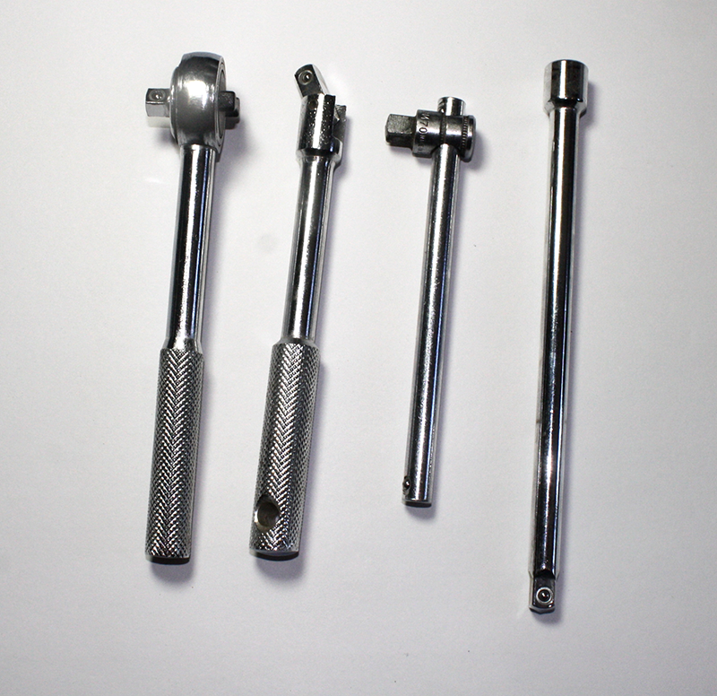
Figure 4-9. 1/4” drive socket handles and extension
An extension is useful if you need to get at a bolt that is beyond the reach of the wrench. Figure 4-10 shows an extension adapter for a 1/2” drive tool. It’s the same idea as the one shown in Figure 4-9, only larger.
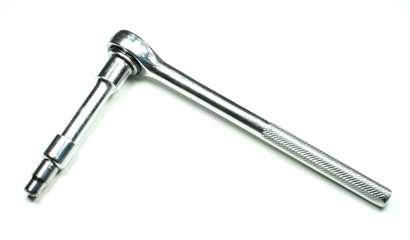
Figure 4-10. Socket wrench with extension
Using pliers of any kind on a screw or bolt intended for use with a socket wrench is a sure-fire way to round off the edges of the head so that no socket will ever work with it again. Some types of pliers have a toothed section supposedly for use on hex-head parts. Don’t use it unless it’s an emergency.
A socket wrench can apply considerable force to a fastener. Be careful not to get too carried away and over-torque the part. The part might be difficult to remove at some future point in time, or even worse, the head of the bolt could shear off, leaving you with a headless bolt and a real problem. If there is a lock washer under the head or the nut, excessive torque can reduce its effectiveness.
A socket should fit snugly on the head of a hex-head bolt or screw, with little or no play (or wiggle). Chapter 2 discussed how a small hex-head fastener, such as a bolt or machine screw, can be difficult to drive if a socket does not seat flush around the head. Small, in this case, means 9/32 of an inch or 7 millimeters, and smaller, and sockets in this size range are usually 1/4-inch drive types.
Most common inexpensive sockets have a slightly rounded edge and angled faces at the entry of the socket that will prevent the socket from fully seating on the sides of the head of a small fastener or bolt with a low-profile head. Consequently, the tool could easily slip and damage the head. Figure 4-11 illustrates this situation. Note how an unmodified (stock) socket doesn’t seat flush on a small hex-head bolt or screw. In some cases, it can be even more extreme than what is shown here.
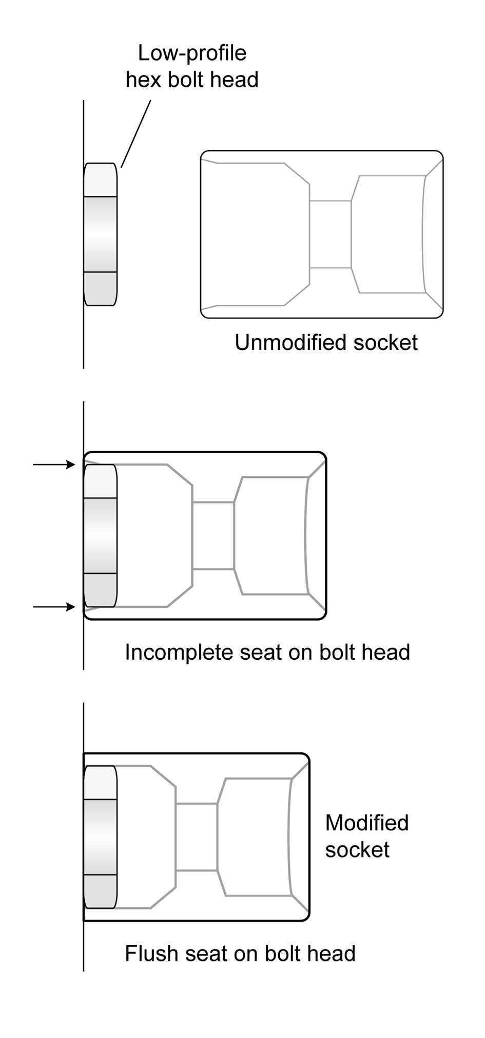
Figure 4-11. Socket seating on a small hex-head fastener
You can modify sockets by grinding off about 1/16 to 3/32 of an inch of the end of the socket, or up to where the interior angles end. The leaves a flat surface at the entry of the socket for the head of the fastener to fit into. Figure 4-12 shows sockets before and after such a modification.
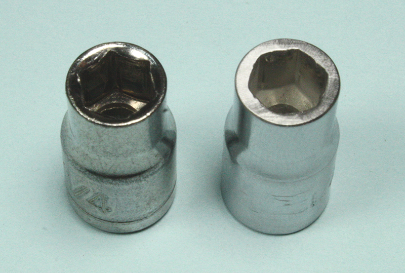
Figure 4-12. Small sockets before and after flush seating modification
Now the modified socket will seat flush on the head of the fastener, as shown in the bottom illustration in Figure 4-11. This isn’t something I’d recommend for sockets larger than about 9/32 inch or 7 millimeters in size. Since the heads on larger fasteners tend to be taller and have more available surface area for the socket to contact, the modification really isn’t necessary.
Adjustable Wrenches
In general, an adjustable wrench is a bad idea, unless you are doing plumbing. But sometimes there is just no other way to get the job done due to space constraints or lack of other available tools. If used correctly and only occasionally, an adjustable wrench isn’t necessarily bad, but it can be used badly.
If you are going to keep an adjustable wrench in your tool kit, make sure it is a good one. This is one tool you don’t want to pick up from the bargain bin, and you should have a selection of sizes. In addition to single tools, adjustable wrenches often come in sets of four with 6-, 8-, 10-, and 12-inch wrenches. Specialty outlets carry 4-inch wrenches, as well. The wrench should have minimal play in the adjustable jaw, operate smoothly without sticking or binding, and look like some care went into its manufacture (forged with smooth machined surfaces).
Figure 4-13 shows the parts of a typical adjustable wrench. The worm drive moves the adjustable jaw in a track cut into the fixed jaw. The adjustable jaw is made so that the seat area will expand or contract while maintaining the correct angle to allow a hex-head bolt to seat correctly. Should you happen to encounter an adjustable wrench that does not maintain the correct angle in the seat, I would recommend tossing it into the recycle bin and getting a better tool.
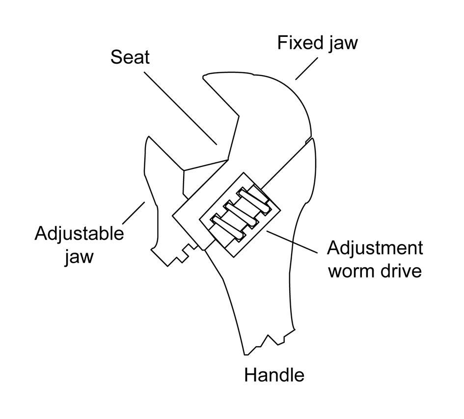
Figure 4-13. Parts of a typical adjustable wrench
If you do elect to use an adjustable wrench, you should make sure that the jaws are tight on the part, and be prepared to stop periodically to check that they remain tight. An adjustable wrench that slips is a fast way to ruin a hex nut or hex-head fastener. Figure 4-14 shows a typical adjustable wrench being used on a large bolt.
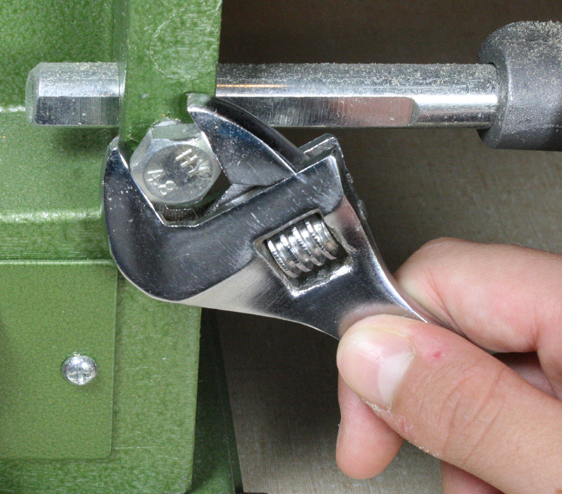
Figure 4-14. A typical adjustable wrench in use
There’s a problem with how the wrench in Figure 4-14 is being used: it isn’t fully seated against the bolt head. Notice that there is a gap between the head of the nut and wrench seat. The bolt head or nut should be as far back against the seat of the wrench as possible.
As with just about any tool, there is a right way and a wrong way to use it. The adjustable wrench is no exception, as Figure 4-15 shows.
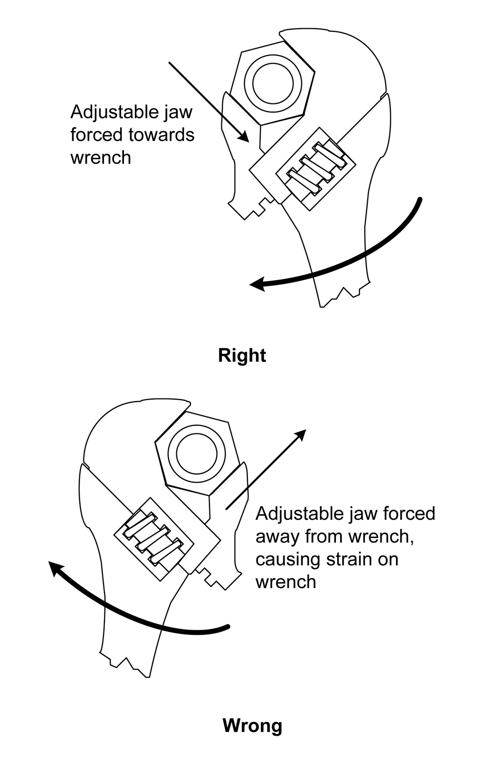
Figure 4-15. Right and wrong ways to use an adjustable wrench
Wrenches (Spanners)
In electronics work, there is usually not much call for a box or open wrench, but as described in Chapter 3, small tools are available. Figure 4-16 shows a set of small open wrenches, ranging from 13/64 to 5/16 inch in size. These are old, so finding a set like this again might take some digging around in a used tool shop.
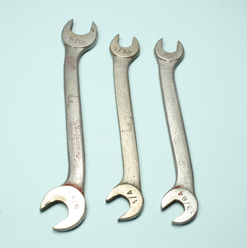
Figure 4-16. Set of small dual-size open wrenches
Figure 4-17 shows a more modern set. These are more conventional combination wrenches, with an open wrench on one end and a box wrench on the other. These range from 1/4 to 5/16 inch in size. Small metric sizes are also available.
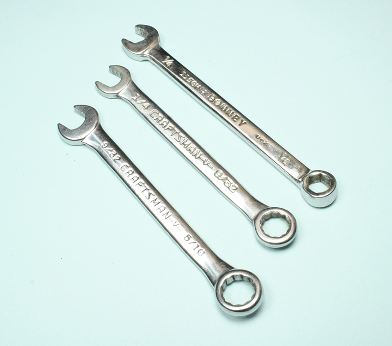
Figure 4-17. Set of small combination wrenches
When you are working with a small wrench, it helps to keep pressure on the tool while it is in contact with the head of the fastener. A finger can be used for this purpose, although a small wood dowel or wood block will also work. Because the working faces of a box or open wrench typically have slightly rounded edges from the forging process used to manufacture them, they might not seat completely on the head of a small fastener. The width of the tool might also prevent it from reaching into tight spaces, such as when you are making an adjustment to something.
The set shown in Figure 4-16 is unique in that the wrenches are already thin and relatively flat, but this is more the exception than the rule. You can modify (hack, if you will) a small wrench to make it thinner by carefully grinding both sides of the open end of the wrench. Figure 4-18 shows a wrench prior to modification.
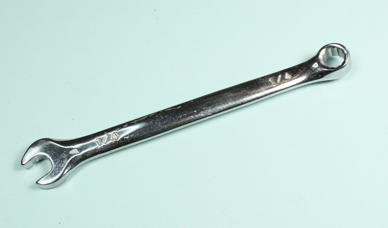
Figure 4-18. Unmodified small 1/4” wrench
A bench grinder was used to flatten the surfaces of the wrench shown in Figure 4-19, and the ground surfaces were then smoothed with a semi-abrasive buffing wheel. This technique can also be applied to the box end of the wrench. In case you’re curious, this was done to a cheap 1/4-inch wrench that happened to be lying about, not doing much.
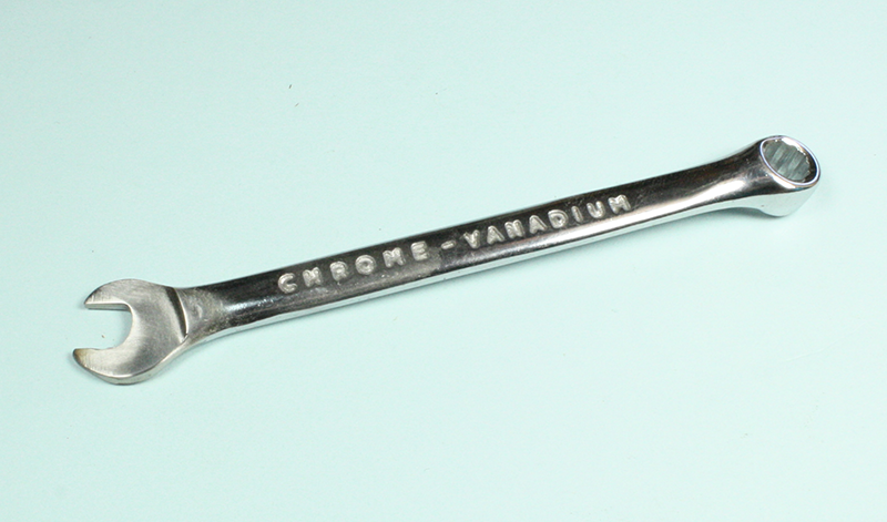
Figure 4-19. Modified small 1/4” wrench
There’s nothing wrong with hacking tools to make them fit your needs. Just be aware that, once modified, the tool will never be the same. But that’s all right if you really need it and don’t mind potentially sacrificing a tool. I generally keep a number of sacrificial tools on hand that I pick up from the bargain bin at the hardware store or scrounge up at one of the local second-hand tool stores. I wouldn’t do this to an expensive tool unless there was a desperate need.
Rivets
Using a blind rivet is simple and the technique is relatively easy to master. In addition to different diameters, blind rivets also come in different lengths, called the grip depth. The thickness of the parts to be joined determines the necessary grip depth. Figure 4-20 shows a blind rivet being set into a steel panel, and Figure 4-21 shows the rivet in place with the stem (or tensioning rod) cut free by the riveting tool. The tensioning rod is still in the barrel of the tool and will fall out when the handle is released.

Figure 4-20. Installing a blind rivet: setting the rivet
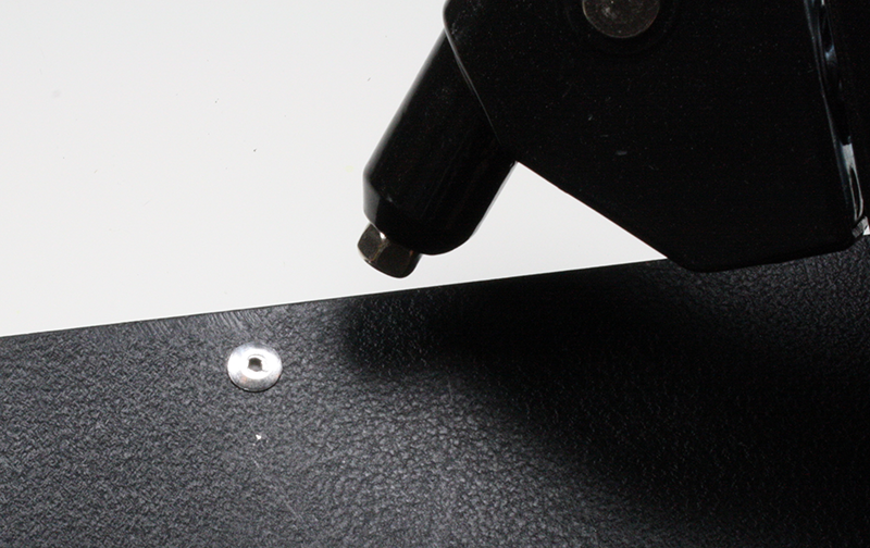
Figure 4-21. Installing a blind rivet: rivet set and stem cut
There are four basic steps involved in installing a blind rivet:
-
Drill holes in both pieces to be joined at the location where the rivet will be placed.
-
Insert the rivet into the riveting tool.
-
Insert the rivet body though the holes in the pieces to be joined.
-
Pull the handle until the tool trims off the rivet’s tensioning rod.
Figure 4-22 shows what is going on when a blind rivet is set. It also shows the two main measurements of a rivet: diameter and grip. The size of the hole in the material to be joined depends on the diameter of the rivet to be installed, which itself depends on how much load the riveted joint will need to bear. It is essential to make a hole that is just large enough for the rivet body to pass through, but not so large that the rivet is loose in the hole.
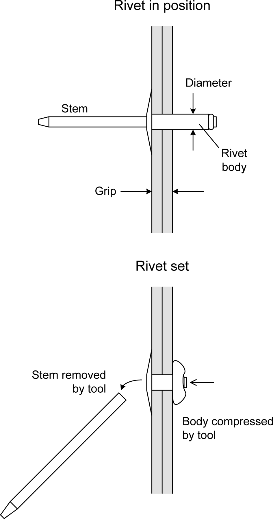
Figure 4-22. Blind rivet installation details
The grip depth is how thick the material can be for a given rivet size. Note that the grip depth is always less than the length of the rivet body. Blind rivets have a specified minimum and maximum grip. The minimum grip is the point at which a shorter length rivet may be used. A given rivet can be used with material that is less than the minimum grip depth, but it will cause the rivet body to “bunch” on the blind side. This might create a problem with other parts, and it can result in a less-than-optimal joint. In some cases, the tool might not be able to pull the tensioning rod out far enough to snap it off, which can be a hassle to deal with. If the grip depth is less than the minimum for a particular rivet, consider using the next shorter size.
The maximum grip is the thickest combination of materials the rivet can reliably and properly hold together. Do not use a rivet with a maximum grip that is less than the actual depth. When the rivet is set, it will not expand the blind side sufficiently to solidly and reliably join the pieces.
Some blind rivet tools come with a handy hole-sizing chart, along with a selection of rivets to start off with. Small rivets won’t take as much stress as larger parts, and there is always the chance that a small rivet might be torn loose under extreme duress. A blind rivet can be used with soft materials such as plastic or even canvas if a backing washer is used to distribute the force exerted by the rivet. Some types of rivets are made with extended flanges for these types of applications. The rivets are cheap, so if you have a blind rivet tool, you really should have a good selection of rivets in different diameters and grip depths to go with it. Make sure you also have the correct drill bits to make the holes for the rivets.
Dealing with Stubborn Fasteners
Work with fasteners long enough, and at some point you will inevitably encounter a stubborn fastener that simply refuses to move. Here are some techniques for dealing with these situations.
Solvents
Using the solvent WD-40 can sometimes loosen parts that are bound by corrosion. There are also other solvents sold for this purpose. Use a cotton swab or small eye dropper to apply it to the base of the head of the stuck fastener.
Bear in mind that WD-40 is not really a good general-purpose lubricant. It is primarily a penetrating oil and was originally developed for water displacement and metal protection for military equipment, such as missiles and aircraft. It’s also good for noisy door hinges, but it will dissolve heavier lubricants like motor oil and grease. Using it on something like a bicycle chain or a bearing is not a good idea.
Parts that have been sitting for a long time sometimes become “frozen” or “seized” in a threaded hole. One way to break them loose, in addition to applying a solvent, is to tap them. Do this using a small punch and a ball-peen hammer. A few taps might be all that is needed to break the part loose and get it moving. Just be careful not to damage the drive slots or the hex-socket hole in the head of the screw or bolt.
Torque
When you are dealing with a tight screw, it sometimes helps to apply a quick, sharp “snap” of force to the tool to break the bolt or screw loose. This requires a solid fit between the tool and the screw. Be careful not to apply an excessive amount of force, or you could be left with either a broken tool or a headless bolt or screw.
Temperature
In some cases, you can loosen a stuck fastener just enough to remove it by cooling it relative to the surrounding material. A can of so-called freeze spray (used in electronics to find temperature-sensitive parts) can suit this purpose. The trick is to apply the coolant directly to the head of the fastener and the metal immediately surrounding it after first applying a solvent. Cool the fastener and the surrounding area until it begins to develop frost, and then use the appropriate tool as quickly as possible. The objective is for the fastener and the hole it is in to contract; the fastener will become slightly smaller in diameter and the diameter of the hole will increase slightly (this might be counterintuitive, but it does work).
Drilling and Grinding
As a true last-resort measure, you can sometimes remove a stuck fastener by drilling out the head or grinding it off. If it is a flat-head screw, then drilling is about the only option. The trick is to drill out enough of the old screw head to pull the pieces it is holding apart, but not so much as to dig into the countersink below the head. Figure 4-23 shows how this is done.
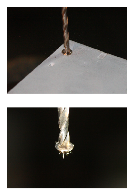
Figure 4-23. Drilling out the head of a counter-sunk screw
The top image in Figure 4-23 shows the drill cutting into the head of the stuck screw. Notice that the diameter of the drill bit is slightly larger than the diameter of the screw shaft. In the bottom image, you can see what is left of the head of the screw on the drill bit. The operation was a success. You can remove what is left of the screw using pliers. Since the objective is to get the old screw shank out and discard it, you can be as rough with it as necessary.
For screws and bolts with raised heads (pan, cap, and such), it is possible to grind off the head of the fastener using a tool like a right-angle grinder (such as the one shown in “Grinders”). Just be careful not to let the grinder make contact with the underlying metal any more than necessary, and even then, some sanding and buffing might be needed to clean up the area. The end result of both procedures is the same: the shank of a now headless screw or bolt will be left that can then be removed and discarded.
Soldering and Desoldering
Soldering is the quintessential activity of electronics. One of the first odors you might notice when walking into an active electronics shop or lab is the smell of the hot flux from the solder wire. Almost every component used in electronics can be connected using solder in one form or another.
Solder Types
Solder is an alloy of two or more metals. In the past, the typical formulation used tin and lead, although nowadays other metals are found in alloys for lead-free solder or special applications requiring high conductivity or strength. The ratio of the component metals varies, depending on the application. In the past, the most common alloy for electronics work was a 60/40 blend of tin and lead (Sn60/Pb40). Another common type has a ratio of 63/37, which has a slightly lower melting point. For plumbing applications involving copper tubing and copper pipes, the ratio is usually 50/50, with a much higher melting point that requires a torch or a substantial soldering tool.
Early on, soldering was used to join copper tubing and the seams of tin cans, and then made the transition to electronics because of its ability to easily create strong, electrically conductive bonds between the metallic leads of components. Because of its lead content, solder was phased out of use in plumbing in the 1980s. Since 2006, lead-based solder has been phased out of most consumer electronics production, as well, although it is still common in high-reliability, aerospace, military, and hobbyist applications. Lead-free formulations are usually some variation of tin-copper (Sn-Cu) or tin-silver-copper (Sn-Aq-Cu). The lead-free types have different melting points than Sn-Pb formulations, although modern soldering irons can easily deal with this. The main issues with RoHS (restriction of hazardous substances—i.e., lead-free) solders involve ease of use and long-term reliability.
Although many people worry about the lead in solder, it’s really not as big a hazard as some might think. In the solder alloy form, the lead is quite stable and poses a minimal hazard if handled properly. The primary concern is ingesting lead. Fermilab (the Fermi National Accelerator Laboratory) has a web page on lead solder hazards. The main points are to never eat or drink anything while working with solder, and be sure to wash your hands after using it. In fact, it’s always a good idea to wash your hands after doing anything on the workbench, since the lead in solder isn’t the only potentially hazardous material found around electronics.
In an editorial in the journal ECN, Jon Titus provides a quick overview of the impacts of making the transition to lead-free solders, most of which have been either neutral or negative. One major point is that to date there has been no data to indicate that lead-based solder is a major contributor to levels of free lead in the environment. The second major point is that lead-free solder joints can be less reliable and and are prone to introducing problems such as “tin whiskers,” which can lead to long-term reliability issues. The original advocates of lead-free solder admit that this is indeed the case. Another interesting editorial, appearing in Electronic Design News (EDN) in 2007, listed and debunked some of the myths surrounding RoHS solder.
If you want to use RoHS solder, there are two main types available. A tin-copper alloy (99.3% Sn, 0.7% Cu) with a flux core is readily available in spools of various sizes. The flux used is the same for both tin-lead and RoHS solders, being either rosin-based or water-soluble. Sn-Ag-Cu (tin-silver-copper) solders are used by a majority of Japanese manufacturers for reflow, wave, and hand soldering in production environments. Kester has a good write-up on the use of RoHS solder for hand soldering.
The RoHS solders tend to not flow as smoothly as tin-lead (Sn-Pb) solder, and most types require a slightly higher working temperature (between 5 to 25 degrees C higher than with Sn-Pb solder). For this reason, some sources recommend that the beginner start off with a Sn-Pb solder and then make the transition to RoHS after gaining some soldering skill.
Although RoHS solder has seen improvements over the past few years, there are still some potential issues with tin whiskers, and because of the inherent properties of the metals involved, it will always be slightly more difficult to work with than lead-based solder. What type you choose to use is up to you.
When you are working with any solder, there will be some smoke. This is not the solder itself, as the soldering temperatures are not high enough to vaporize the metals in the solder. The smoke is coming from the flux. It’s still not a good idea to breathe a lot of it, so having a small fan on the workbench will disperse it. Don’t waste your money on a soldering iron with a “fume collector” attachment. These usually don’t work (except for the really expensive industrial-grade tools), and in any case, a cheap fan from the local drugstore will blow the fumes away and keep you cool at the same time.
Tin-lead solder is still readily available and easy to work with and, provided that you don’t ingest any, relatively safe to use. For electronics work, the most common form of solder is a wire with a hollow core filled with a flux material, typically some type of rosin (similar to what violinists use on their bows). Figure 4-24 shows a one-pound spool of rosin flux core solder. RoHS solder is also available in spools like the one shown in Figure 4-24.
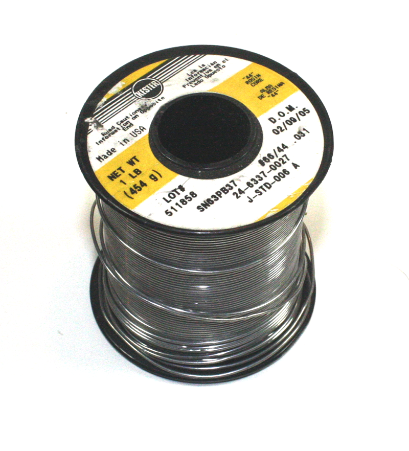
Figure 4-24. Spool of solder wire
For working with surface-mounted components, solder paste is essential. This is basically ground solder with flux and a binding agent that can be applied to the component mounting locations on a circuit board using an applicator. Solder paste is available in RoHS formulations as well as conventional tin-lead. Some solder paste comes in tubes that allow you to squeeze out what you need, or you can find it in small containers with screw-on lids. Figure 4-25 shows a tube of solder paste with a set of spare applicator tips.
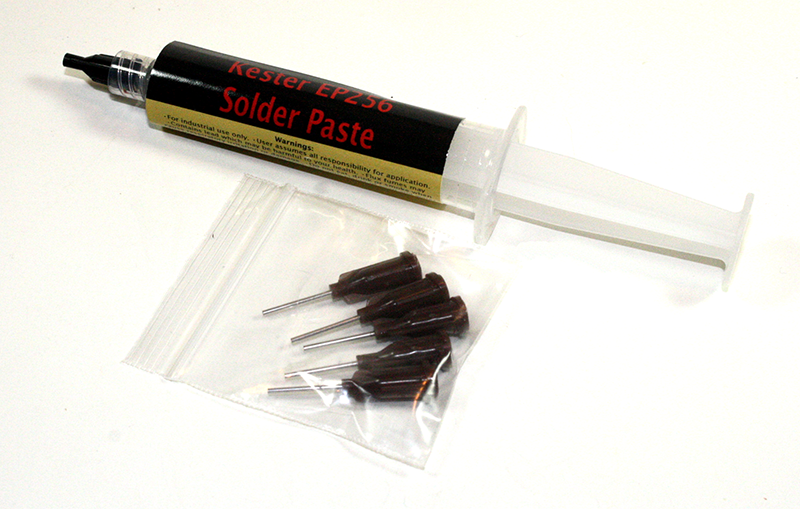
Figure 4-25. A tube of solder paste
Soldering Technique
Chapter 3 covers soldering tools—namely, the soldering iron and soldering stations. If you want or need to work with lead-free solder, then investing in a good temperature-controlled soldering station would be a good idea. A selection of different tip sizes is also wise, since in some cases a fine tip is necessary (e.g., for surface-mount work). In other cases, you might need to apply much more heat (e.g., soldering to the terminals on a large toggle switch), so a large point or chisel tip would be appropriate.
Temperature
One of the questions that often comes up regarding soldering is how hot the tip should be. A general answer might that the tip of the soldering iron should be as hot as necessary to melt the solder and create a solid joint without damaging the part being soldered (or the underlying PCB). Fortunately, soldering has been around for a while, so there is a sizable body of knowledge (and advice) available to draw upon.
The melting point of 60/40 tin-lead solder is around 374°F (190°C), but the tip of the soldering iron needs to be much hotter than that, because it will cool rapidly when applied to the parts to be soldered. However, if the temperature is too high (as is sometimes the case with cheap, unregulated irons), the solder might not flow correctly, and the tip of the iron might not wet (take a thin initial layer of solder) properly.
Some sources recommend a tip temperature of around 700°F (370°C). For some work, you might want it hotter—for example, when soldering 18-gauge wire to a large switch or high-current connector of some type. If you are using RoHS solder, the tip will need to be hotter to adequately melt the solder. A hot iron will allow a connection to be made more quickly, which means the tip of the iron is in contact with the work for a shorter period of time than if the temperature were lower.
Another approach is to set the temperature to around 550°F (260°C) and increase it until you obtain the desired result. But bear in mind that if the temperature is too low, you risk damaging something because of the extended time necessary to heat the joint to the point where the solder will flow. The objective is to find the temperature range that works for you in typical situations. If you have a soldering station with a digital readout, I suggest keeping a list of temperatures for different tips and types of soldering activities, which you have determined for yourself, taped up near it.
Soldering Wires
Soldering can take some practice to master. Unfortunately, it is not as simple as just applying some heat and daubing on some solder. When you are soldering, you are, in effect, brazing, albeit at a low temperature. The idea is to get the work (the parts to be soldered) hot enough to let the solder melt and flow across and between them. The solder forms a bond with the metal of the components being soldered and becomes hard after it has been heated. Figure 4-26 shows a wire being attached to the connector lug of a small pushbutton switch.
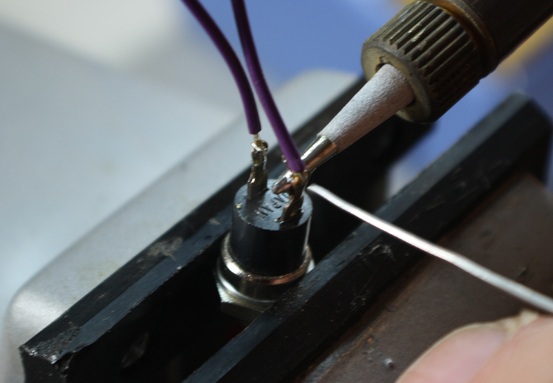
Figure 4-26. Soldering wires to a switch
After the wires have been soldered to the switch, the solder lugs are covered with heatshrink tubing, as shown in Figure 4-27. This protects the connections and prevents things from accidentally making contact with them. Using heatsink on a bare connection like this is always a good idea, even though it is an extra step.
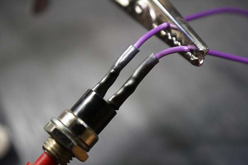
Figure 4-27. Finished switch wiring with protective heatshrink tubing
Soldering a PCB
Soldering parts to a printed circuit board can be challenging. Unlike wires, the components on a PCB tend to be heat sensitive, so leaving the soldering iron on the connection for too long can potentially do some damage. Figure 4-28 shows a component being soldered to a PCB.
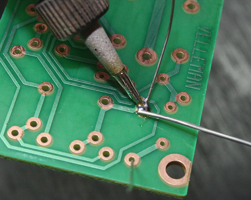
Figure 4-28. Soldering a component to a PCB
The place on a PCB where the lead of a component goes through is called a pad. A hole that exists in a PCB solely for the purpose of connecting one layer to another (like a vertical jumper of sorts) is called a via. PCBs come in single-layer, double-sided, and multilayer forms. Chapter 15 discusses the design of PCBs.
In Figure 4-28, you can see that the solder is applied to the point where the tip of the soldering iron meets both the component lead and the connection pad on the PCB. This happens to be a single-sided PCB, which can be slightly more difficult to solder than a double-sided PCB. In this case, the flux core in the solder was sufficient to help create a solid connection, but sometimes additional flux helps. Figure 4-29 shows the result for two components (a resistor and a small diode on the other side).
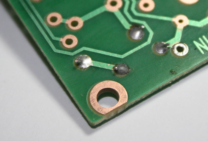
Figure 4-29. Component soldered to a single-sided PCB
A single-sided PCB can be tricky to solder, since there is little reason for the solder to wick down into the hole alongside the component lead. This can result in an incomplete connection, where only a part of the component lead is actually soldered and the solder flows around the rest of the lead without bonding.
It is not uncommon for the solder on a single-sided PCB to form a slightly rounded mound. This is because the solder does not flow down into the hole alongside the lead, but instead tends to form a “puddle” on the PCB pad. You can reduce this (if it bothers you) by using some additional flux and increasing the heat of the soldering iron.
With a double-sided (or multi-layer) PCB with plated-through holes in the pads, the solder should flow through the hole and form a fillet, or sloped fill, on each side of the PCB. The fillet will be largest on the side where the solder was applied and might not be visibly obvious on the component side of the PCB, but the solder should still flow through and fill the hole. Figure 4-30 shows a diagram of what a PCB solder connection should look like. Your results may vary, but the general idea is to have the solder flow through the plated hole in the pad along the component lead.
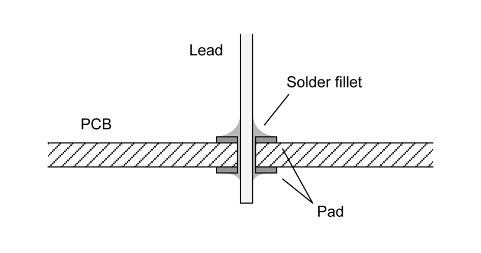
Figure 4-30. Through-hole solder joint for a double-sided PCB
Although some sources state that you should heat the pieces being soldered before applying the solder, it helps if the tip of the soldering iron is “wetted” with some solder before it is applied to the work. Without a good thermal connection, the work will take too long to heat up, and that heat will be transferred into something that could be damaged. Practice will allow you to experiment and see what works best for you, but I recommended using a wetted iron tip and applying the solder to the point where the tip meets the parts being soldered. The solder will melt and flow as soon as the tip and the work pieces reach an appropriate temperature.
When you are working with a PCB, and a single-sided PCB in particular, it helps if the PCB is clean—really clean. Wiping it down with 90% isopropyl alcohol will remove any residual oil or other contaminants. It also helps if the component leads are clean. Lastly, applying paste or liquid flux can make things go more smoothly, but it does leaves a mess that has to be cleaned up when the soldering is complete. Figure 4-31 shows a small container of paste flux that can be applied with a wood toothpick or a thin stick made from a wood-handle cotton swab (use the bare end, or just cut off the swab). I use the Puritan brand 6-inch wood shaft swabs, which can be purchased online through Amazon in packs of 1,000 for about $15 or less.

Figure 4-31. A small container of paste flux
After soldering, it is a good idea to go over the connections with a cleaning solution or just with 90% isopropyl alcohol, particularly if additional flux was used. A small brush, called an acid brush, is commonly used for this task. It is typically used to apply paste flux compounds for soldering copper tubing and pipes, but it is also used in the electronics industry for PCB cleaning applications. You can purchase acid brushes at electronics suppliers, hardware stores, and plumbing supply stores. They are also available in packs of 6, 12, or more from various online sources. I like to trim about 1/4 to 1/3 of an inch off the end of the brush to make it stiffer.
It is a good idea to remove leftover flux from the PCB after you have finished soldering, because flux can attract moisture and dirt. Also, if the humidity and temperature are just right, leftever flux residue can conduct a weak current, which introduces noise into a circuit and possibly cause erratic behavior.
Alcohol and other cleaning solvents tend to leave a white residue on a PCB if it isn’t flushed off completely. This is just flux residue that was deposited when the solvent evaporated. It is a good idea to remove it, and one way to do that is to go over the board with a dry acid brush. Another way is to wash the board in distilled water while brushing it. So long as there are no parts, such as potentiometers or switches, that might have problems with trapped water it won’t hurt anything, and distilled water is nonconductive. Just make sure the board is completely dry before you apply power.
Soldering Defects
If the solder is disturbed while still molten, it can disrupt the solder’s internal structure and create a rough-looking connection, or joint. Also, if the work is not hot enough, the solder won’t flow properly, and the result will be a joint that is weak and might not conduct current reliably. This is called a cold solder joint, and an example is shown in Figure 4-32.
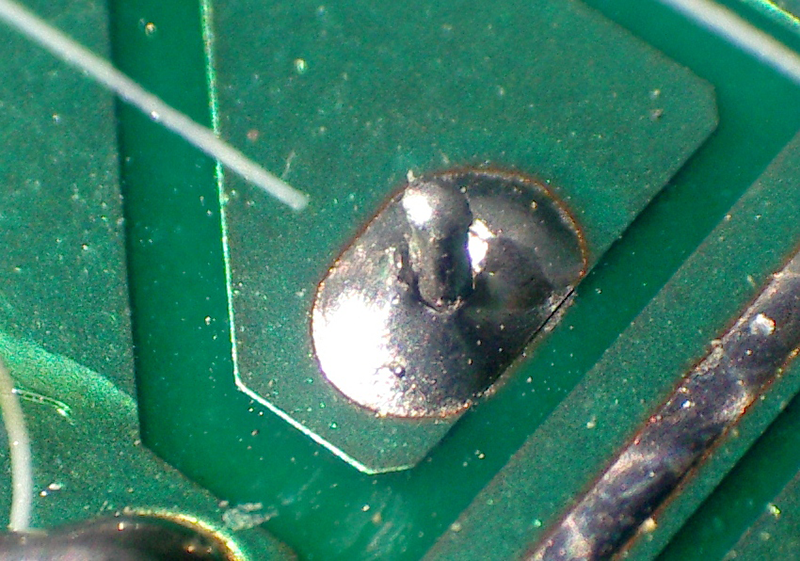
Figure 4-32. Cold solder joint1
When applied correctly, the solder should flow (literally) across the work, leaving a smooth, shiny joint. If the solder is applied quickly enough, the risk of thermal damage to components can be minimized. When the surface of the solder is grainy or dull, it indicates that the component lead may have moved before the solder cooled sufficiently, or the soldering iron wasn’t hot enough. Although a cold solder joint might look like it is solid, it really isn’t, and can lead to a broken joint down the road.
Although not as common as cold solder joints, broken solder joints can also occur. This happens when the lead of a through-hole component breaks free of the surrounding solder on a pad or terminal, often taking some of the original solder with it. This type of defect is typically seen when a circuit board has been subjected to shock or vibration. It was once quite common in portable electronics with single-sided PCBs but is less common with double-sided or multi-layer PCBs and does not occur with surface-mounted components. A cold solder joint can be the precursor to a broken solder joint.
This type of problem can be difficult to track down, as it might be intermittent. Figure 4-33 shows what to look for on a PCB if you suspect that you might have a broken solder joint.
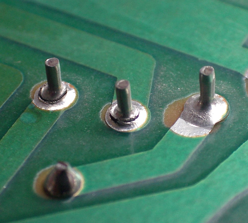
Figure 4-33. Broken solder joints2
To fix a cold solder joint or a broken joint, I recommend that you use some paste or liquid flux and apply a small amount of additional solder while reheating the joint. The flux will help to remove any existing contamination and oxidation, and the new solder will help to melt and reflow the original solder. Figure 4-33 illustrates an additional problem: the pad on the right has lifted from the PCB (delaminated). Since the solder joint appears to be solid, this can possibly be saved with the application of a small amount of epoxy. If this is a double-sided PCB, the opposite side will likely need some rework, as well.
Desoldering Wires and Through-Hole Parts
There are basically two ways to remove solder and free a part: wicking and suction. Wicking involves the use of a copper braid, called (as you might guess) solder wick. Figure 4-34 shows a spool of solder wick.
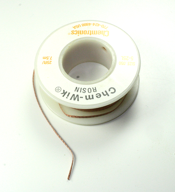
Figure 4-34. Solder wick
The suction method involves a tool of some sort capable of pulling molten solder away from a pad or terminal using a temporary vacuum. The tools available include a squeeze bulb, a spring-loaded device called a desoldering pump (known colloquially as a solder sucker), and soldering repair and rework stations with built-in vacuum pumps. Figure 4-35 shows a typical hand-operated desoldering pump (and, as usual with my tools, it’s seen some use over the years—but it still works just fine).
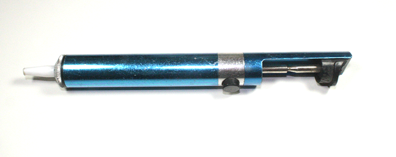
Figure 4-35. Typical desoldering pump
I don’t consider the squeeze bulb to be of much use, so I won’t discuss it here. If you want to try it, by all means do so. The technique is basically the same as that used with a spring-loaded desoldering pump, but it’s been my experience that the bulb is just not as effective in terms of creating a quick vacuum to pull off the old solder. I’m also not a big fan of most soldering rework stations with a built-in vacuum pump. The concept is good, but often the execution leaves something to be desired. There are some good rework stations on the market, but they tend to be really expensive. The wick and the solder pump will work for almost every desoldering job that might come up, and they are cheap and easy to find.
Solder wick is relatively easy to use, but it does take a bit of practice to get it right each time. The first step is to make sure the solder joint is clean. Use some isopropyl alcohol to remove any residual dirt or grease. Next, apply the soldering iron and maybe a wee bit of solder to remelt the connection. Then, while the joint is still hot, place the wick on it as shown in Figure 4-36. The soldering iron is pressed down on top of the wick and the molten solder should flow up into it. Sometimes it helps to apply a little bit of liquid or paste flux to help get the solder flowing smoothly. This is what the gooey stuff around the pads happens to be, and in this case it was liquid flux from a tube.
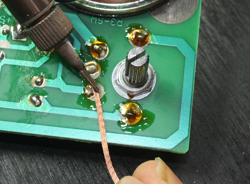
Figure 4-36. Desoldering with solder wick
The spring-loaded desoldering pump has been around for a long time. The early types didn’t always work very well, but newer models have better seals on the internal plunger and more durable tips. The tip is made from a high-temperature plastic, so while it is possible to melt it, it takes some effort to do so.
To use the desoldering pump, first cock it by pushing down on the plunger until it locks. Then simply heat the solder connection until the old solder melts, quickly place the tip of the pump over the joint, and release the plunger. Figure 4-37 shows a desoldering pump in action.
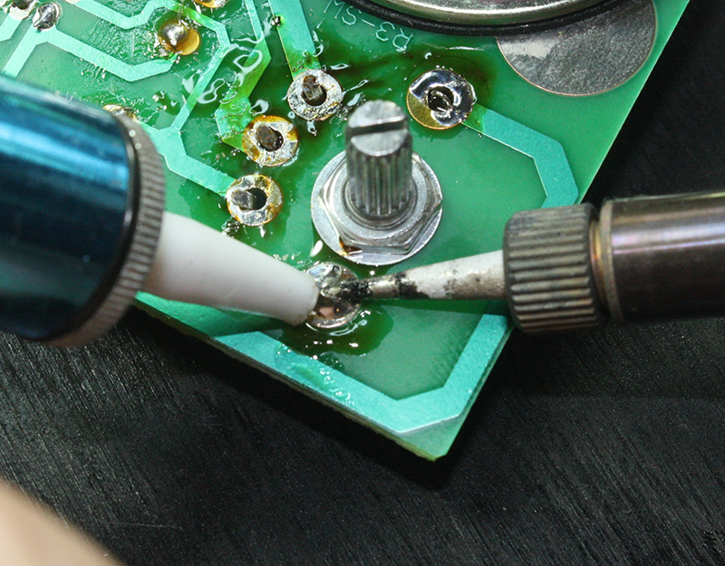
Figure 4-37. Using a desoldering pump
As with the solder wick, using a desoldering pump is not something you can expect to master the first time (or second, or third). It take practice to develop a “feel” for when the solder is the right temperature and the best angle to use for placing the tip of the tool on the solder joint. In Figure 4-37, the tip of the pump is being held just above the pad while the iron melts the solder. It is then immediately placed on the molten solder and the trigger is pressed to release the plunger. Figure 4-38 shows the result.
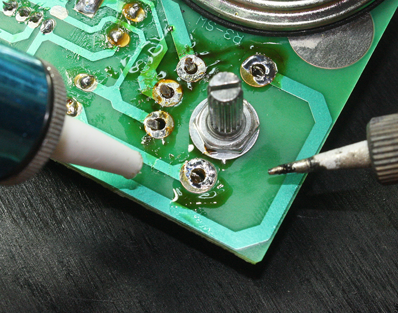
Figure 4-38. Result of using a solder pump on a large pad
In case you’re wondering, the images in this section came about because a potentiometer was mounted upside down on a PCB. It needed to be removed and reinstalled on the other side of the board. The operation was a success and it works correctly now.
Surface-Mount Soldering
Soldering surface-mount technology components (or SMDs, surface-mount devices) correctly and reliably by hand requires a considerable amount of practice and skill, but it can be done for many types of SMT components. You will need the correct type of soldering iron and tip, solder paste, a magnifier of some sort, tweezers, and a steady hand. Chapters 8 and 9 describe SMT component packages.
The first step is to apply the paste where the component will attach to the PCB, as shown in Figure 4-39. It doesn’t really take much paste to do the job, but a little extra doesn’t really hurt anything. It just makes things a bit messier and makes more work for the clean-up step.
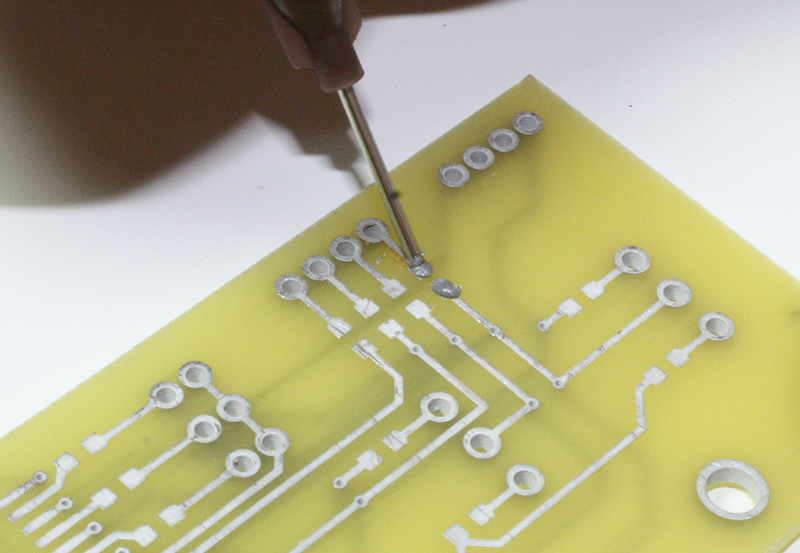
Figure 4-39. Applying solder paste
Next, position the part (in this case, a resistor) in the correct location, setting it on and slightly into the paste. The binder in the paste acts as a weak glue, holding the part to the PCB, as shown in Figure 4-40.
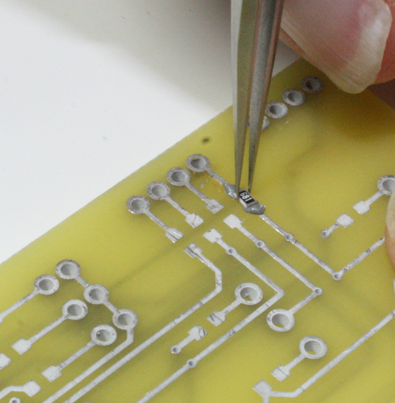
Figure 4-40. Setting a part on the solder paste
While holding the part down with the tweezers (or something similar), apply the tip of the soldering iron to each end of the part. Be sure to touch the tip to both the part and the underlying PCB so that they will both heat at the same time. The paste should melt and flow onto and under the part, as shown in Figure 4-41.
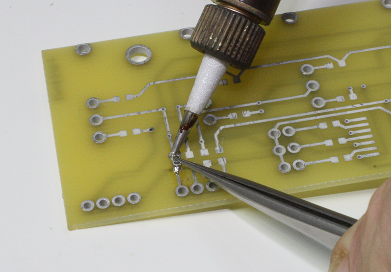
Figure 4-41. Soldering one end of an SMT resistor
When complete, the final result should look like Figure 4-42. Your part might have one end slightly raised, but that’s all right for a manual soldering job. The main objective is for the part to be securely soldered to the PCB with bright, shiny solder joints.
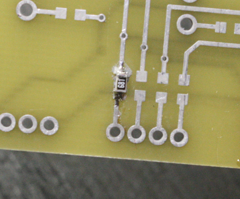
Figure 4-42. Soldered surface-mount resistor
Soldering a surface-mount integrated circuit (IC) to a PCB is trickier than a single resistor. The first step is to apply solder paste to all of the connection points on the PCB, as shown in Figure 4-43.
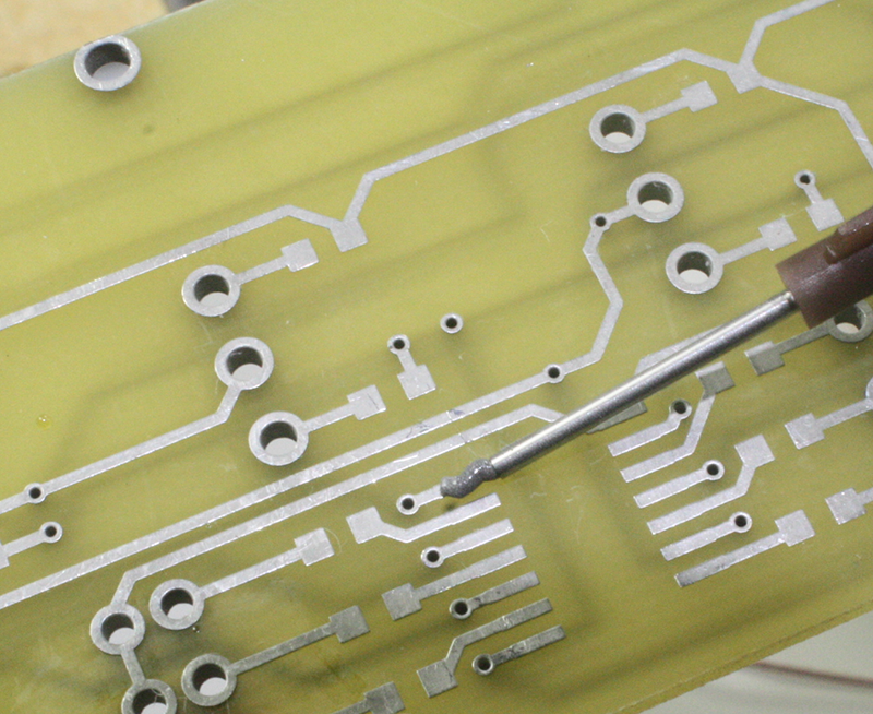
Figure 4-43. Applying solder paste for a surface-mount IC part
You want to apply just enough paste to make a good solder joint, but not so much that the part “floats” on the paste. In other words, it should settle close to the PCB when it is placed on the paste-covered pads, with little extra paste oozing out from under the leads of the part.
The reason for the close initial fit is to avoid having to force down the leads of the IC to meet the underlying PCB during soldering. If this happens, there is a definite possibility that they will spring back up when the soldering iron tip is removed, undoing the soldering job and making for a situation where you might spend considerable time trying to figure out why something works only intermittently.
To solder the IC, apply a fine-tip soldering iron to each lead of the IC, holding it only long enough for the paste to melt and flow. In Figure 4-44, a tool made of high-temperature plastic is being used to hold the part and keep it aligned on the PCB pads. The first pin is now finished and the tip of the iron is being pulled away. This will be repeated for each of the pin on the IC. Notice that another part has already been soldered to the board. It looks nice because it was cleaned up after soldering with alcohol and a brush.
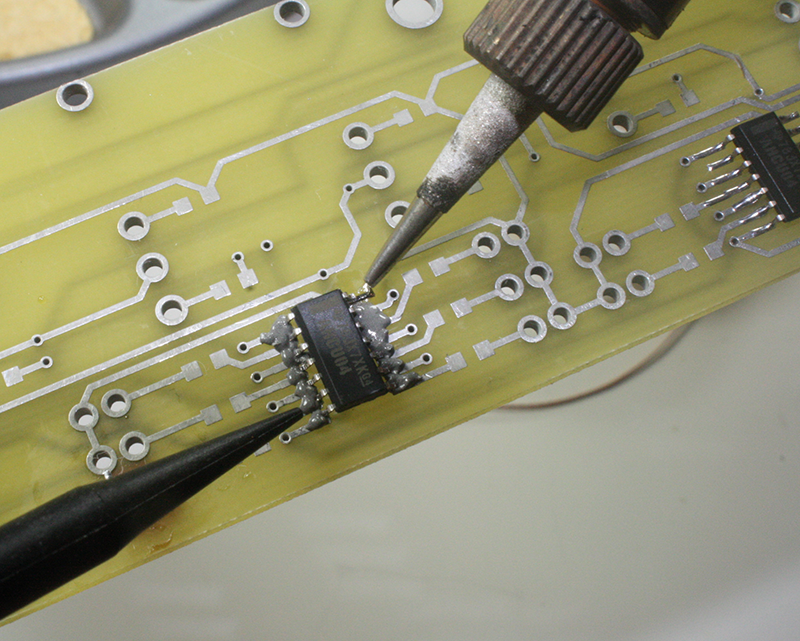
Figure 4-44. Soldering a surface-mount IC part
When the soldering is finished, you can use a razor knife with a fine tip to test each lead for a solid connection. None of the leads should lift when pried gently with the tip of the razor knife.
Figure 4-45 shows what a finished surface-mount IC should look like when it is soldered to the PCB correctly. It might be necessary to clean up around the IC using a brush and a cleaning solvent, as discussed in “Soldering a PCB”.
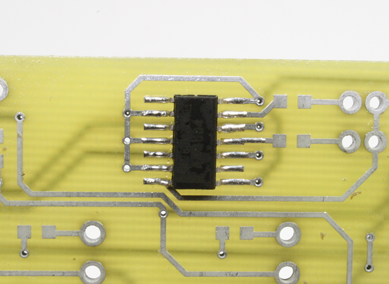
Figure 4-45. Soldered surface-mount IC
The SMT workstation shown in Figure 3-44 has both a temperature-controlled soldering iron and a hot-air attachment (there is a small pump inside the unit to provide a constant flow of air). A surface-mount part can be soldered (and desoldered) with the hot-air tool once it is set into the solder paste. This actually makes for cleaner connections with less leftover residue to clean up, but it does require a somewhat pricey workstation, and a fair amount of practice. Figure 4-46 shows the hot-air tool with a tip mounted on the end. The tool comes with a selection of tips with orifices of various diameters.
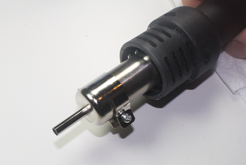
Figure 4-46. Hot-air tool for SMT soldering and desoldering
This tool can be used to solder an SMD IC to a PCB, provided that the temperature and air flow are set correctly. It takes some practice and experience to be able to define just what “correctly” means in each situation and with different models of SMT soldering tools. The preliminary steps (cleaning the PCB and applying the solder paste) are the same as before with the soldering iron.
When using a hot-air system, you should still hold the part down, mainly to prevent the air flow from moving it once the solder starts to melt. Use metal tweezers or a high-temperature tool made specifically for this purpose, like the one shown in Figure 4-44.
When you are doing hot-air soldering, it is important not to use too much solder paste. Not only does this reduce the mess you will need to clean up afterward, but the less solder to be melted the better. The hot-air nozzle isn’t as discriminating as a soldering iron, so it is possible to heat not only the leads of the part, but the entire part as well. If you do elect to purchase one of these tools, you should also be prepared to buy a couple of tubes of solder paste and several surface-mount practice kits, and spend some quality time with it.
There are some surface-mounted components that simply cannot be soldered by hand. These include ball-grid array (BGA) parts or other package styles with connection points underneath the body of the part. Some types of connectors and inductors are made like this, and they can be difficult to solder manually as well. In these cases, you should probably consider paying someone with an SMT reflow soldering system to mount the parts for you. If this person has what is called a pick-and-place machine available, he or she can also populate and solder an entire circuit board automatically. The set-up costs for such a process can be significant, however, so it might not be practical for a one-off board. Still, most fabricators that deal with surface-mount production have people on staff who can manually place the parts on one or two PCBs and then put them through the reflow soldering machine.
Manual surface-mount soldering can be tedious, and it requires patience and a steady hand. For some applications, it is unavoidable, particularly if the parts you want to use come only in surface-mount packages. On the other hand, if you are building a prototype or just a one-off where size isn’t a big issue, then opt for the through-hole or point-to-point soldering techniques, if possible.
Surface-Mount Desoldering
To be perfectly honest, without a hot-air tool like the workstation shown in Figures 3-44 and 4-46, desoldering any surface mount part with more than two connection points can be a major challenge, if not nearly impossible. The reason for this is that a SMD with multiple leads really needs to be desoldered all at once. Solder wick or a pump can get some of the solder, but it is difficult to get at the solder under tiny gull-wing or J leads. One technique involves heating and lifting each lead using a fine-tip razor knife, a large pin (e.g., a hat pin), or needle-point tweezers. This is tedious, to say the least, and with a J-lead part it can effectively ruin an otherwise reusable part. If the part uses metalized connection points under the body of the part, then using a razor knife, pin, tweezers, solder wick, or a pump is not a viable option.
Figure 4-47 shows the hot-air attachment for an SMT soldering station in use as a desoldering tool. You use the air flow to heat all of the part’s leads at once by moving it around the part in a tight circular motion while applying pressure under the part with needle-point tweezers. There are also tools and attachments for the hot-air nozzle made specifically for this purpose that are not shown here.
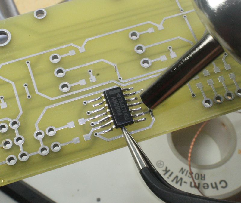
Figure 4-47. Desoldering a surface-mount IC with hot air
Once the solder under all the leads has melted, the part can be lifted off and set aside to cool. The PCB will probably need some cleanup with alcohol and perhaps the removal of leftover solder with solder wick.
Provided that the part wasn’t heated too severely, it might still be usable, although excessive heat can stress the silicon chip inside the part and possibly cause some of the ultra-fine wires that connect it to the outside leads on the package to become unreliable. I keep a special parts bin just for “suspect” parts that have been removed from a PCB. They might work, and they might not, but if I’m in a hurry and willing to gamble, and component failure isn’t a big deal, then I can dig through the bin and see if there’s something I can use.
Cutting
The term cutting covers a lot of ground, ranging from dealing with things like rod, bar, and sheet stock, to cutting something to modify it. There are techniques for each situation, some better than others.
Rod and Bar Stock
Cutting small-dimension metal rod and bar stock, in the 1/8-inch to 1-inch range, is easily accomplished with a miniature cut-off tool like the one shown in Figure 4-48 (also described in Chapter 3). This type of tool is sometimes called a saw, but it is actually a type of grinder. It is relatively inexpensive, and it produces a clean, even cut through the material. The shield has been raised in Figure 4-48, so you can see the cutting wheel and the clamp.
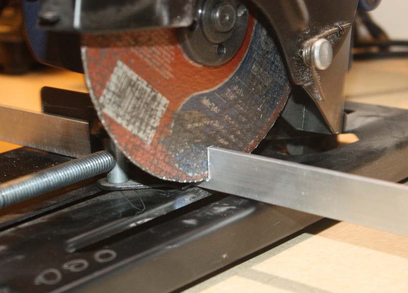
Figure 4-48. Miniature cut-off saw in action
Notice that the miniature cut-off saw has a clamp built into its base. It is a good idea to use it—always. If you have a saw like this without a clamp, it would be wise to get one or improvise something. The reason is that, although it is small, this saw can produce a lot of torque, and it can easily throw a loose work piece across the room (or at you!). It can also remove fingers without too much effort, so you really don’t want your hand near the blade trying to hold something down while you cut it.
There are different types of cutting wheels available for small cut-off saws. These aren’t really blades, but rather thin grinding wheels. The level of abrasiveness is specified as the grit. A coarse grit, between 40 and 50, will cut heavier material, but it won’t make a really fine cut. A finer grit, about 60 or so, will make a smoother cut, but it can overheat if used to cut thick material.
Some small cut-off tools are made to work with both blades and abrasive wheels, while others, like the one in Figure 4-48, use an abrasive wheel only. Since this tool is used only for cutting metal, there is no need for a toothed blade. There are other, larger, tools available with 7.25-, 8-, or 10-inch-diameter toothed blades for cutting non-metallic materials.
Alternatively, you can use a bench vise and a hacksaw, as shown in Figure 4-49. The secret to a clean cut is to make sure that the material is firmly clamped, the saw blade is sharp, and you have applied some form of lubrication. Trying to cut something by holding it down by hand on the bench might work with soft plastics, but it doesn’t always work so well with metal. The hacksaw blade will tend to bind, bounce, and “chatter” on hard materials, resulting in a rough cut that might require additional work (grinding and sanding) to make it usable.
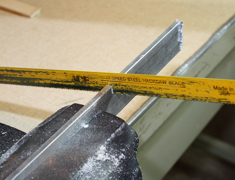
Figure 4-49. Cutting with a hacksaw
Move the blade of the hacksaw through the material with even strokes, and use the entire length of the blade. Let the teeth on the blade do most of the work for you. If cutting metal, go slowly—no more than about one stroke per second. The saw blade can get quite hot, even with a lubricant, and excessive heat can ruin the blade. The saw blades of the impatient have many dull and flattened teeth.
For a typical hacksaw blade, the cutting action occurs only on either the push or pull stroke, depending on how the blade was mounted in the hacksaw frame. I prefer to have it cut on the inward stroke (i.e., when pulling the saw toward you), somewhat like a Japanese woodworking saw. You might want to try it both ways and see which is best for you. Figure 4-50 shows the common names for the various parts of a typical hacksaw. Note that this type differs from the one shown in Figure 3-33, which is a more compact version.
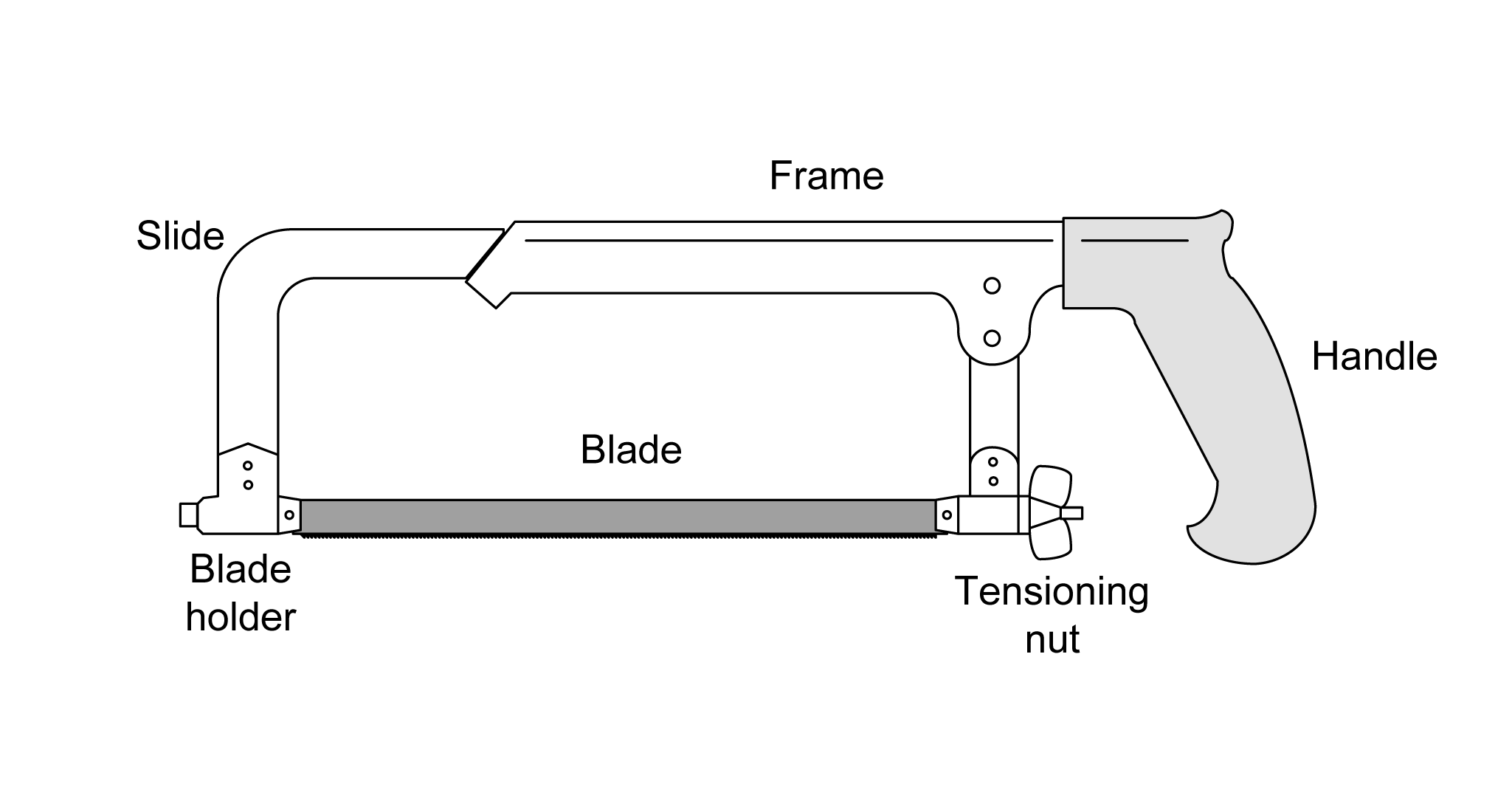
Figure 4-50. Parts of a typical hacksaw
Hacksaws like the one shown in Figure 4-50 have a sliding section of the frame that allows for different length hacksaw blades. The slide usually has two or three stop positions. In the US, blades are readily available in 10-inch (250 millimeter) and 12-inch (300 millimeter) lengths. The number of teeth per inch (or centimeter) is another specification, and you can get blades with 14, 18, 24, and 32 teeth per inch (TPI). The coarse blades are good for cutting thick metal, while the finer pitches are useful for making finer cuts and working with thin materials.
Using a lubricant when cutting metal with a hacksaw is always a good idea. A light oil works well. Table 4-7 lists lubricants for drilling, but these can also be applied to cutting with a hacksaw. The only exception might be the use of alcohol with aluminum. In that situation, I would recommend mineral oil or some other light oil. I like to use a bottle of oil with an extendable spout tube.
Lastly, make sure the blade is correctly tensioned in the saw frame. There is usually a wing nut at one end for this purpose. A loose blade might bind or create a ragged cut, so the blade tension should be tight, but not too tight. It is tight enough when the wing nut becomes too tight to easily turn by hand. Don’t use a tool to make it tighter, as this could cause the blade to break or damage the frame.
Sheet Stock
You can cut material such as sheet plastic with a pair of heavy-duty shop shears like the tool shown in Figure 4-51. These are useful for cutting thin material such as sheet brass or copper, soft plastics, and wire mesh.
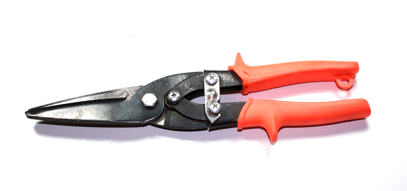
Figure 4-51. Heavy-duty shop shears (straight cut)
Generally speaking, plastic sheet, such as the polystyrene in Figure 4-52, is easy to cut, so long as it is not too thick. The shears will split the material and lift one side up along one of the blades, but thick material will not lift as easily, and the shears could bind. If the plastic sheet is too thick for the shears to deal with, then it’s time to consider another approach, such as the rotary tool (see “Rotary Tool”), or the bench shear shown in Figure 4-55.
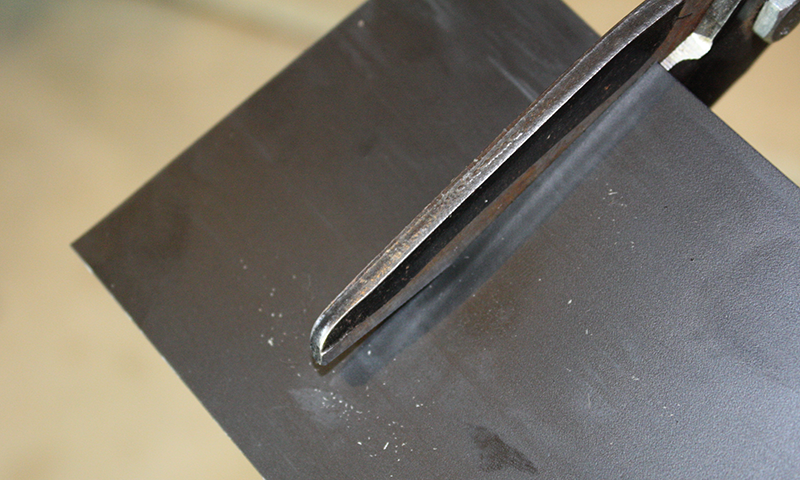
Figure 4-52. Using shop shears on sheet plastic
Sheet metal, unless it is very thin, can be a real pain to cut, even with special-purpose, aircraft-type sheet-metal cutters like those shown in Figure 4-53. These are also known as snips in some circles. These tools come in three forms: left, right, and center. Each type is designed to cut a curve in a particular direction (or no curve at all).
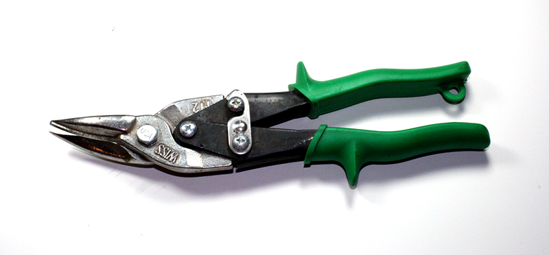
Figure 4-53. Aircraft-type metal shear (aviation snip)
Because metal is a stiff material, some effort might be required to make the cut. As with the shop shears shown in Figure 4-51, the metal shears will push up one side of the material as it is cut. It is easier to cut off a small section of the metal sheet, around 1/4-inch wide, and work into the desired depth in a series of shallow cuts. Trying to cut directly through a sheet of aluminum or thin steel from a starting position several inches into the material might be difficult, depending on the thickness of the material. In Figure 4-54, the cut was started deeper into the sheet because it was thin. If it had been thicker, it would have been easier to make a series of shallower cuts to get to the desired width.
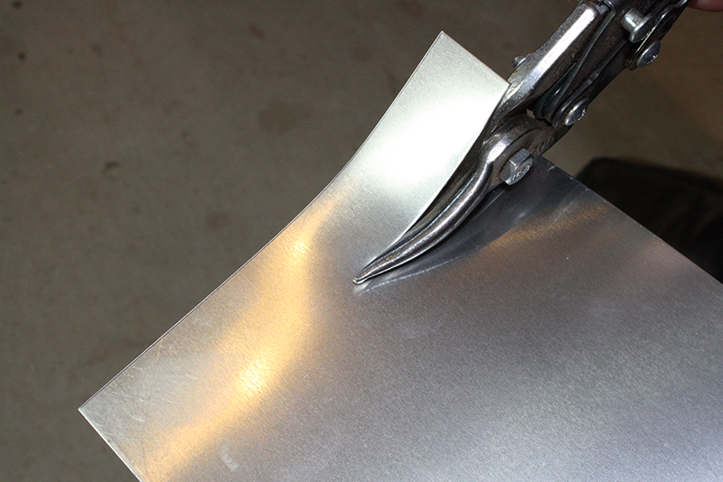
Figure 4-54. Using aircraft-style metal shears
Hand-held shears, or nippers, are handy for quick jobs or trimming something to make it fit, but the best solution for cutting both plastic and metal sheet stock is a bench shear, like the one shown in Figure 4-55. If you can justify purchasing one, then by all means do so. A good bench shear can save a lot of time and give the end result a professional appearance. This particular tool can also serve as a brake, which is useful for bending sheet metal into complex shapes.
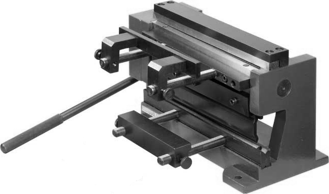
Figure 4-55. Small bench shear/brake tool
A nibbler-type tool is yet another way to cut sheet metal. These tools come in manual, electric, and pneumatic forms. Figure 4-56 shows a manual nibbler tool.
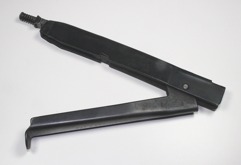
Figure 4-56. Manual nibbler tool
A nibbler works by literally nibbling away the material, one small bite at a time. For thin materials and short cuts, this tool can do a decent job, but for anything more substantial, you might want to consider using an electric or pneumatic-type nibbler tool. A manual nibbler tends to be hard on the hand after just a short time. You should also be prepared to clean up the cut with a file or a grinding attachment on a rotary tool. Nibblers don’t always make clean, even cuts, but with some practice, they can do a decent job.
Last, but not least, is the rotary tool. For short cuts in thin material, it can do an acceptable job. Refer to “Rotary Tool” for suggestions and examples of ways to get better control of a rotary tool and produce clean cuts. If you need a long, straight cut (6-inch or more), then you really need a bench shear like the one shown in Figure 4-55. The alternative is to make the best cut possible with the appropriate tool and then clean it up with a file, a grinder, or a bench-mounted belt sander.
Drilling
There’s more to making a good hole than just eyeballing a drill bit and grabbing the power drill. By “good hole,” I mean one that will fit the part correctly, be it a screw, a bolt, an LED, a switch, or anything else that needs to go through a hole. If the hole is too small, it will need to be drilled again, which is not a disaster, but can be an annoyance. If the hole is too large, the part will simply fall through it, and there are not many options available to recover from this kind of mistake.
Selecting A Drill Size
The appropriate size (diameter) of a drill bit depends on what you want to use the hole for. If you want a clearance hole (where something passes through it without interference), the bit needs to be slightly larger than the parts you want to use. If, on the other hand, you intend to tap the hole so that it will accept a threaded part, it needs to be sized correctly to allow for the tap to cut threads inside the hole to the correct depth.
For example, a clearance hole for a 6-32 machine screw would need to be no larger than 0.1495 inch, which is a #25 drill. If the hole will be tapped to hold a 6-32 screw, then it should be 0.1160 or 0.1065 inch in diameter, depending on the depth of the thread cut you want.
The tap drill sizes shown here are for both 50% and 75% taps. A 50% tap means that the threads will engage to 50% of their depth. This is usually more than enough for most uses, and because the tap tool doesn’t cut as deeply, there is less risk that it will bind and break off in the hole during tapping. For very shallow holes, you might want to consider using a 75% tap. These are harder to create, but they will hold the fastener more securely when only a few thread turns are engaged. Also be aware that some drill and tap size tables give the 75% drill size, not the 50% size.
Table 4-2 shows a basic tap drill size chart for UTS/ANSI sizes. The drill index refers to the standard numbering system used for drill bits. Note that there are no fractional equivalents for these drill sizes.
| Thread size | 50% drill index | 50% drill size | 75% drill index | 75% drill size |
|---|---|---|---|---|
2-56 |
49 |
.0730 |
50 |
0.0700 |
4-40 |
41 |
.0960 |
43 |
0.0890 |
6-32 |
32 |
.1160 |
36 |
0.1065 |
8-32 |
27 |
.1440 |
29 |
0.1360 |
10-24 |
20 |
.1610 |
25 |
0.1495 |
Table 4-3 shows UTS/ANSI clearance drill sizes. These are mainly recommendations, but they are used throughout industry. If you don’t have access to the specified index drills, choose a fractional drill size that is large enough to allow the screw or bolt to slide through but not so large that the head of the fastener falls through as well. The index sizes listed will produce what is called a free-fit hole (i.e., it will be somewhat loose). Most of the fractional sizes listed are closer to the tight clearances for each screw size. In the case of the 6-32 screw, there is no fractional size drill that is close, so a 9/64 drill might create a hole that is a little too tight, and the 5/32 might be too loose. Start with the 9/64 and see if it works for you. You can always make a hole larger with a file or a reamer, but you can never make a hole smaller.
| Thread size | Drill index | Drill size | Nearest fraction |
|---|---|---|---|
2-64 |
41 |
.0960 |
3/32 |
4-40 |
30 |
.1285 |
1/8 |
6-32 |
25 |
.1495 |
9/64 or 5/32 |
8-32 |
16 |
.1770 |
11/64 |
10-24 |
7 |
.2010 |
13/64 |
Table 4-4 shows some common tap drill sizes for metric hardware and Table 4-5 lists some common metric clearance drill sizes.
| Screw size | 50% metric drill size | 75% metric drill size |
|---|---|---|
1.5 × .35 |
1.25 |
1.15 |
1.6 × .35 |
1.35 |
1.25 |
1.8 × .35 |
1.55 |
1.45 |
2 × .4 |
1.75 |
1.6 |
2 × .45 |
1.7 |
1.55 |
2.2 × .45 |
1.9 |
1.75 |
2.5 × .45 |
2.2 |
2.05 |
3 × .5 |
2.7 |
2.5 |
3 × .6 |
2.6 |
2.4 |
3.5 × .6 |
3.1 |
2.9 |
4 × .7 |
3.5 |
3.3 |
4 × .75 |
3.5 |
3.25 |
4.5 × .75 |
4.0 |
3.75 |
5 × .8 |
4.5 |
4.2 |
6 × 1 |
5.4 |
5.0 |
7 × 1 |
6.4 |
6.0 |
8 × 1.25 |
7.2 |
6.8 |
9 × 1.25 |
8.2 |
7.8 |
10 × 1.5 |
9.0 |
8.5 |
| Screw size | Metric drill size | Closest American drill index/size |
|---|---|---|
1.5 × .35 |
1.65 |
52 |
1.6 × .35 |
1.75 |
50 |
1.8 × .35 |
2.00 |
5/64 |
2 × .4 |
2.2 |
44 |
2 × .45 |
2.2 |
44 |
2.2 × .45 |
2.4 |
41 |
2.5 × .45 |
2.75 |
7/64 |
3 × .5 |
3.3 |
30 |
3 × .6 |
3.3 |
30 |
3.5 × .6 |
3.85 |
24 |
4 × .7 |
4.4 |
17 |
4 × .75 |
4.4 |
17 |
4.5 × .75 |
5.0 |
9 |
5 × .8 |
5.5 |
7/32 |
6 × 1 |
6.6 |
G |
7 × 1 |
7.7 |
N |
8 × 1.25 |
8.8 |
S |
9 × 1.25 |
9.9 |
25/64 |
10 × 1.5 |
11.0 |
7/16 |
Drilling Speed
The appropriate rotational speed of a drill bit depends on the size of the drill, the type of drill, and what it is cutting.
For example, for a standard twist drill (the most common type) used in a drill press with aluminum or steel, the nominal speed varies from 3,000 RPM for a small (1/16 inch) drill down to 600 RPM for a 5/8-inch drill cutting steel. In general, the larger the drill, the slower the speed. Table 4-6 shows suggested speeds for various drill sizes and materials.
| Drill size | Acrylic | Aluminum | Steel |
|---|---|---|---|
1/16 – 3/16 |
2,500 |
3,000 |
3,000 |
1/4 – 3/8 |
2,000 |
2,500 |
1,000 |
7/16 – 5/8 |
1,500 |
1,500 |
600 |
Controlling drill speed with a hand-held variable speed power drill is difficult, at best. Most hand-held cordless drills top out at around 1,500 RPM, while corded drills can reach 2,500 RPM. When drilling a small-diameter hole with a hand-held drill, you typically want to run the drill as fast as it will go and keep the drill bit well lubricated.
Drilling Thin Sheet Stock
When drilling holes in thin sheet stock (like the cover panels on some types of electronics enclosures) you should use a drill press, and the panel to be drilled should be sandwiched in between two sheets of heavier material, like thicker aluminum sheet or 1/2-inch-thick pieces of hardwood. Clamp it all down securely using C clamps. Figure 4-57 shows the concept behind this technique.
The benefits of this technique are that the hole will be cleaner (less jagged fringes) and the sheet metal won’t be distorted by the pressure of the drill bit. You can also use just a bottom support to help reduce distortion. The downside with both approaches is that you will have to sacrifice a piece or two of material to your drill press. I recommend keeping a box of scraps near the drill press and just continue reusing them until they are too full of holes to keep around any longer.
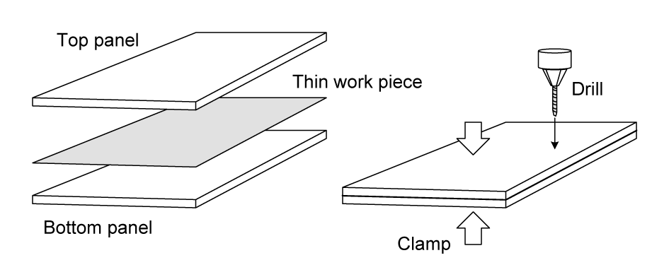
Figure 4-57. Drilling thin sheet metal between sacrificial panels
If this sounds like a lot of work just to drill a hole, well, it is. But even if the hole will be filled and covered by something like a switch or a knob, thin sheet metal can still distort a significant distance outward. The ideal solution is not to use thin sheet metal panels, but there may be times when that just can’t be avoided.
Lubricants
If you are cutting through hard metal, such as steel or tempered aluminum, a lubricant is a very good idea. Overheating a drill bit is a sure way to ruin it.
Some drill presses found in machine shops have a built-in lubricant pump and reservoir tank, but for the rest of us, a can of machinist’s lubricant will do. If you are using a drill press and the work piece is clamped securely, you can apply the fluid yourself; otherwise, you’ll need an assistant to help with the lubricant while you hold the drill.
You can pick up a can of tapping or cutting fluid at any well-stocked hardware or home improvement store, or even purchase some online. WD-40 also works well as a drilling lubricant, as does kerosene or rubbing alcohol when you’re working with aluminum.
Just remember to continuously apply it to prevent overheating due to excessive friction.
A large syringe is sometimes useful in this case, as is a 1/2-inch or 1-inch-width brush along with a small metal can to hold the lubricant. In the past, it was common to find a cut-off soup can sitting next to a machine tool with kerosene or cutting oil in it and a small brush resting in the fluid.
Always check to make sure the cutting oil or lubricant you want to use is compatible with the material to be drilled.
Table 4-7 lists some drilling lubricant possibilities for different types of materials.
| Material | Suggested lubricant/cutting fluid |
|---|---|
Aluminum |
Kerosene |
Isopropyl alcohol |
|
Mineral oil |
|
Copper |
WD-40 |
Light machine oil (sewing machine or turbine oil) |
|
Mineral oil |
|
Brass |
WD-40 |
Light machine oil |
|
Mineral oil |
|
Iron |
SAE 10 or SAE 20 oil |
Light machine oil (with flow) |
|
Purpose-made cutting fluid |
|
Steel |
SAE 10 or SAE 20 oil |
Light machine oil (with flow) |
|
Purpose-made cutting fluid |
The SAE 10 and SAE 20 grade oils should be nondetergent motor oil. Do not use standard motor oil as a cutting oil, as it contains detergents and other agents. Also avoid the multi-viscosity oils (i.e., the 10W-40 type).
When Table 4-7 states “with flow,” it means that the lubricant should be constantly flowing over the drill as it cuts into the material. The flow rate for something like the light machine oil doesn’t need to be heavy, but drilling through iron or steel can generate a lot of heat, so using a brush might not be sufficient. Softer materials (such as aluminum, copper, and brass) are easier to drill without creating a lot of friction heat, so long as they are lubricated.
In general, lighter lubricants need to flow constantly when used with hard materials, and the lighter the lubricant, the more that needs to flow. This helps to prevent the build-up of heat (which is the main purpose of the lubricant), and lighter fluids will tend to burn off or evaporate faster than heavier lubricants. In any case, don’t let the drill bit run dry, or you could end up with a dull or ruined bit.
Some machine tools use water-based cutting lubricants (called emulsified coolants) that flow constantly from a nozzle on a flexible tube that can be aimed at the tool. Other machines, like large multi-axis computer-controlled tools, operate inside an enclosure in a constant spray of coolant. For most tasks in a small shop, a brush or wash bottle and a selection of easy-to-obtain lubricants is usually fine.
Most of us don’t have fancy machine tools with built-in lubricaton systems, but from the preceding discussion and Table 4-7, you can see that sometimes just drilling a hole with a standard drill press can use a lot of lubricant. The question then arises: where does all that lubricant go? I use an old rectangular cake pan for my miniature drill press; the entire tool is small enough to sit in it. For the other tools that don’t need massive amounts of oil or kerosene, I use paper towels and place them where they will catch the drips. The large drill press uses a plastic tub that sits on the floor under the work table of the press. Some tools, such as manually operated vertical mills and lathes, have catch basins built into the frame of the machine for just this purpose.
If you are interested in the technical details of the effects of lubricants, and cutting fluids in particular, a paper from Michigan Technical University discusses the effects of cutting fluids on heat transfer.
Punches and Pilot Holes
When you are drilling metal, it is a good idea to start with a punch point. This reduces the chance of the drill bit “walking” away across the surface of the material by giving it an indentation to settle into. The automatic punch described in “Specialty Metalworking Tools” is an ideal tool for this. A center punch and a ball-peen hammer also works to create a starting point for drilling.
When you are drilling large holes, a pilot hole is a good way to align a larger drill. Typically you would want your pilot hole to be about 1/4 to 1/3 the diameter of the drill to be used to make the final larger hole. This provides enough of a hole for the larger drill to seat into. When you’re using a hand-held drill, if the pilot hole is too small, the larger bit can jump out and go for a walk across the surface of the material. If you are drilling a very large hole, then you may need to create a sequence of progressively larger pilot holes.
Using a Step Drill
Using a step drill, like the ones shown in “Specialty Metalworking Tools”, correctly is an incremental process. This is particularly true when you’re drilling into metal. The first step is to create a pilot hole large enough to accommodate the smallest step on the drill bit. Then, using generous amounts of lubricant, work each step of the drill bit into the material with a pause in between to allow the bit to cool.
Using a step drill bit in a hand-held drill is somewhat problematic, depending on the material you are drilling into, as a step drill might have a tendency to bind and good control of the drill is necessary to prevent this. If you do elect to use a step drill bit in a hand-held drill, make sure to maintain a tight grip on the drill at all times and don’t plunge the bit. Let the bit do the work for you as much as possible.
Common Drilling Problems
Drilling a hole sounds like a simple thing, and for the most part it is. But there are some traps for the unwary even with something this simple. The biggest things to watch out for are overheating, chatter, binding, and walking. Most of what is discussed in the following sections applies to drilling metal. Wood and plastic have their own set of similar issues, but metal is the most challenging.
Overheating
Attempting to drill through hard material like steel can result in a lot of friction. This, in turn, creates a lot of heat. In some cases, the resulting heat can damage the material being drilled, and it can definitely ruin an otherwise good drill bit. If you don’t have any lubricant handy, then try to make the hole in small increments, rather than have at it all in one go. When drilling multiple holes in thin sheet steel, pause between each hole to allow the drill bit to cool off.
Chatter
Chatter is a serious problem with a hand-held drill, but not so much with a drill press. Chatter can occur when you attempt to drill a large hole without first drilling a pilot hole. For holes larger than about 1/8 inch in diameter, always drill a small pilot hole first. If, for example, you are trying to drill a 1/2-inch hole in a piece of 1/8-inch-thick tempered aluminum plate, start with a 1/8-inch drill, then go to a 1/4-inch, followed by a 3/8-inch drill, and then use the 1/2-inch drill as the last step. As the bit gets larger, the drill will be harder to control, so large holes are best done on a drill press, if at all possible.
Binding
A close relative of chatter, binding can occur when you’re drilling a large hole and the bit attempts to take out more material than the drill motor can handle. On a drill press, this can stall the spindle and cause the drive belt to slip. It is particularly dangerous with a hand-held drill, because when the bit binds, it can rip the drill out of your hands and break fingers. Use the same step-up technique as described for chatter to help reduce the chance of a bind and possible injury.
Walking
A spinning drill bit will have a tendency to move across a surface unless there is a starting dimple (via a punch) or a pilot hole to help keep it in place. This is called walking, and with a hand-held drill it can result in a marred surface.
Dull Drill Bits
It seems that people (myself included) are constantly buying new drill bits to replace those that have become dull and useless. When a drill bit becomes dull, it will no longer cut correctly and will instead just spin and get extremely hot. Even bits used just for wood will dull over time. This is more of a problem with hard woods, although soft woods also take a toll. Composite materials like MDF (medium-density fiberboard), MDO (medium-density overlay), and Masonite can also wear down a drill bit. The materials used for printed circuit boards tend to be hard on drill bits, which is why PCB fabricators will replace their drill bits on a regular basis.
When you’re working with metal, the first line of defense against dulling is to use lubricant. For woods and other materials, there isn’t too much you can do about it, except to occasionally sharpen dull bits and try to avoid overheating. In the past, a drill bit was sharpened with a file and a vise, and the process was tedious and time consuming. It also took a fair amount of practice to get it right. Another method uses a large bench or stand grinder, possibly with a fixture to hold the drill bit to the grinding wheel at the correct angle. Doing this by hand is possible, but not recommended.
There are different types of drill-bit sharpeners available, some better than others. This is an area where you definitely get what you pay for, as the cheap drill-bit sharpeners are better at leaving a drill bit in worse shape than they are at actually sharpening a bit correctly. If you find yourself hunting through a collection of drill bits for one that is still sharp, or purchasing new bits on a regular basis, then you may want to consider buying a good sharpener.
Here are a few tips to avoid dulling drill bits:
-
Do not overheat the bit. Cut a little, back off a little, then cut some more. Don’t try to plunge all the way through thick material in one go. If the bit starts to smoke, it’s definitely too hot.
-
When drilling through metal, use a lubricant or a cutting oil. Use more lubricant for harder metals such as iron, steel, and tempered aerospace-grade aluminum.
-
Keep your drill bits clean. Leftover bits of metal and wood (and wood sap) can act as abrasives and wear down the cutting edges of the bit.
-
Use the appropriate drill speed for the material. Table 4-6 lists some suggested speeds for various drill sizes and materials.
Taps and Dies
If you are using screws or bolts with matching nuts or prethreaded holes, you don’t need to worry about tapping a hole to create an internal thread. But if you need to attach something like a bracket to a heavy piece of material and there is no easy way to get behind the hole to attach a nut, then tapping the hole is a viable approach.
When you are drilling a hole to be tapped, it is essential to select the appropriate drill bit, as discussed in “Selecting A Drill Size”. If the hole diameter is too small, the tap might bind and break off in the hole, and it is extremely difficult to remove a broken tap. Conversely, if the hole diameter is too large, the threads will not be deep enough to reliably grip the screw or bolt, and it might pull out under stress.
Tapping a hole is fairly straightforward. Once a hole of the correct size has been drilled, the appropriate tap tool is screwed into the hole with the tap handle provided with the tap and die kit. If you drilled for a 50% hole, then the tool should go in without too much resistance. A 75% hole will require more force, since it is cutting through more material to create the threads inside the hole.
Use plenty of lubricant when tapping threads. Never try to tap a hole if the tool is dry. Even with a 50% hole, there’s a small chance the tool might bind if there is no lubricant, and once that happens, there is a distinct risk that you might break the tap tool off in the hole while trying to extract it. A broken tap is extremely difficult to extract. In some cases, it’s better to make a new hole and simply grind the broken tool flush with the surrounding surface.
As an example, let’s look at the process of creating a tapped hole for a 6-32 machine screw. Figure 4-58 shows the piece of aluminum to be used, along with an automatic punch immediately after the drill point mark is created. Figure 4-59 shows the work piece clamped to the table of the drill press, and a #34 drill bit is being used to drill the hold. I elected to use a #34 drill bit instead of a #32 (50%) or a #36 (75%), mainly because I didn’t have a #32 handy. The result will be somewhere between a 50% and 75% tap cut.
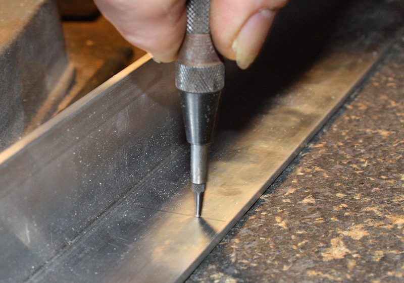
Figure 4-58. Preparing to drill a hole for tapping
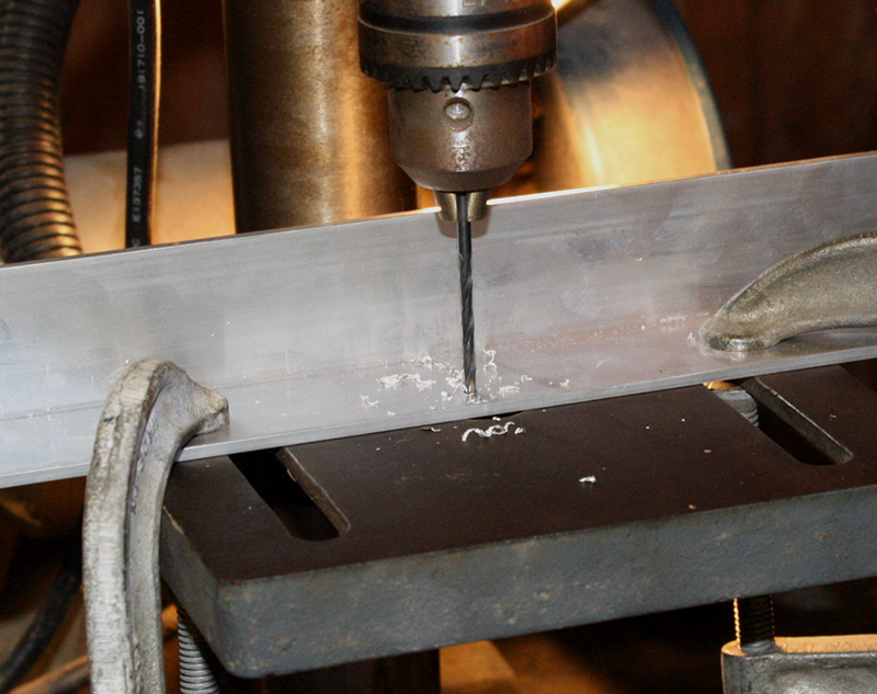
Figure 4-59. Drilling a hole for tapping with a drill press
In Figure 4-60, the hole is drilled, and tapping can commence. Note that I used a thin lubricant during drilling—rubbing alcohol (isopropyl), in this case. In Figure 4-61, the work piece has been moved away from the drill chuck with the clamps still in place (the work table of most drill presses can swivel on the main post of the press) and the tap has been mounted in the tap handle. This special tool usually comes with a tap and die kit, but can also be purchased separately (as this one was).
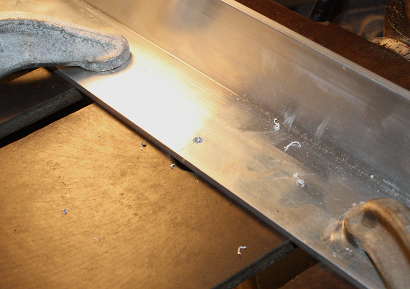
Figure 4-60. Drilled hole ready to tap
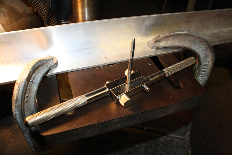
Figure 4-61. Tap mounted in tap handle tool, ready to go
Figure 4-62 shows the tap completely through the hole, and again notice that I’ve used plenty of lubricant, this time light oil. Last, in Figure 4-63, a 6-32 pan head screw has been inserted to check the tap. After the residue from the lubricant is cleaned off, the part is ready to use.
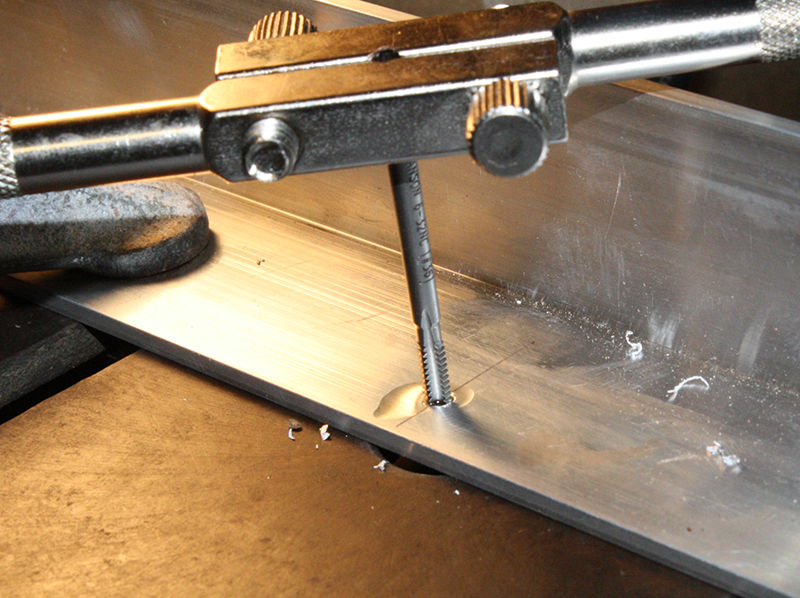
Figure 4-62. Tapping complete, ready to back the tool out of the hole
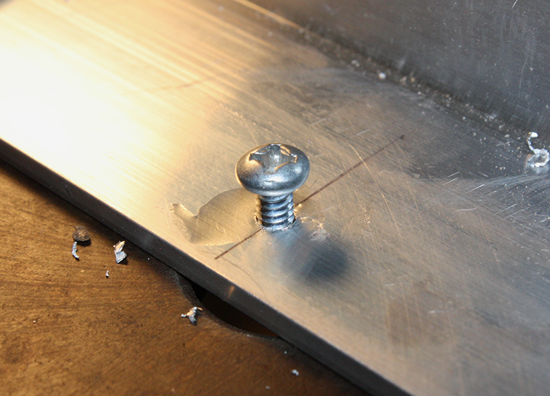
Figure 4-63. Checking the tapped hole with a 6-32 pan-head screw
Make sure the axis of the tap stays aligned with the hole, and always try to make the tap vertically. Trying to tap a hole at an angle can bind the tool and cause it to break, and once the alignment is lost, it’s very difficult to correct it using a hand-tapping tool. This is one of reasons that machine shops use tapping fixtures, as described next. In Figure 4-62, the tap appears to be nonvertical relative to the work piece, but it really is lined up vertically; it’s the image that isn’t vertical.
If you find yourself doing a lot of tapping, you might want to invest in a bench-top tapping fixture made specifically to hold the tap in constant alignment. Figure 4-64 shows a diagram of typical tool of this type. It is also possible to use the chuck of a lathe or drill press to align and hold a tap while you turn the chuck manually (power is off). There are also how-to videos and articles online that describe how to build your own hand-tapping fixture. The whole idea is to keep the tap in alignment with the hole.
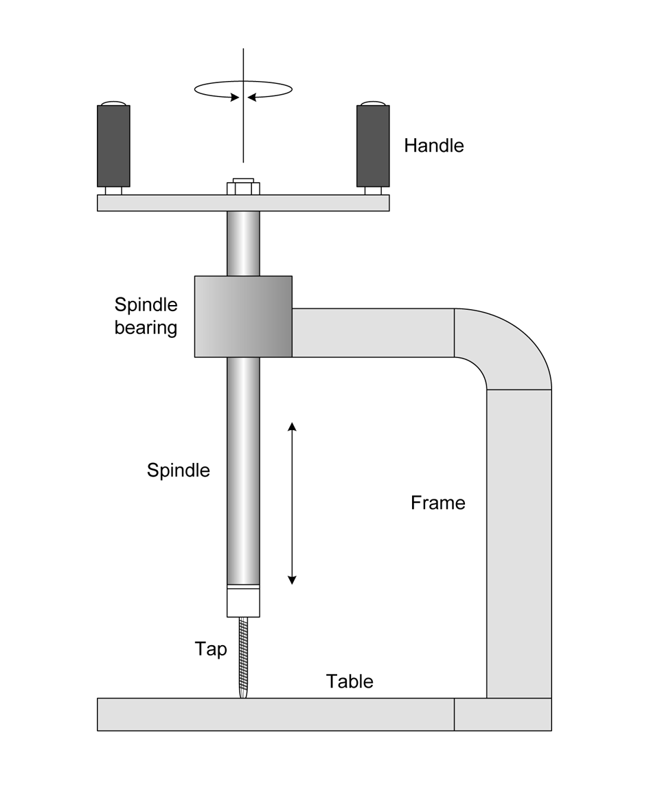
Figure 4-64. A bench-mounted tapping fixture
The fixture in Figure 4-64 uses the weight of the spindle assembly to apply a small amount of downward force to the tap, and the cutting threads of the tap itself will pull it into the work piece. It might take a small amount of pressure to get the tap started, but for the most part, all you need to do is turn the spindle using the handles. A hole in the table at the base of the fixture allows the tap to pass completely through the work piece, and there is usually some kind of clamp arrangement or perhaps a small vise (not shown here) to hold the work piece securely.
There are automated and semi-automated power-tapping tools available. These turn up mostly in machine shops and on assembly lines. Some people have also built their own power-tapping machines using cordless drills and screwdrivers. But for these tools to work correctly and reliably, everything has to be just right. The hole has to be exactly the right size and depth, and the work piece has to be held in exactly the right place. Lastly, the tool needs to be able to stop at the correct depth, reverse the tap rotation, and then back it out of the work piece. Commercial versions of these tools aren’t cheap, so for most of us, it comes down to doing it the hard way by hand.
The counterpart of the tap is the die, and if you need a threaded rod that cannot be purchased at the hardware store, then this is the tool to reach for. For example, consider the situation in Figure 4-65. Here we have a steel rod with some threads at each end. This might be used as part of a linear position sensor (as described in Chapter 8 in the discussion of linear potentiometers), or perhaps it is a tie rod for the steering on a robot. While you could find a steel rod with full end-to-end threading, that might not be what you really want. With a die, you can make a rod like the one in Figure 4-65 to meet your requirements.
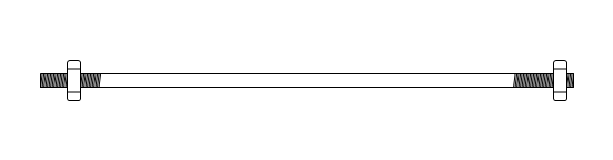
Figure 4-65. Steel rod with threaded ends
Using a die is relatively straightforward, but be forewarned that getting good results when cutting threads by hand is not easy. It takes practice and a fair amount of patience to get it right. In other words, it can be a real challenge.
Figure 4-66 shows a die for cutting 10-24 threads along with the holder it mounts into. Some people suggest grinding a slight taper into the end of the rod to allow it to feed into the die more easily, and I would agree with this. It’s very difficult to convince a die to start to “bite” into a rod without a taper at the end.
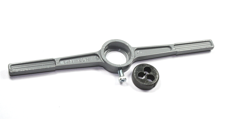
Figure 4-66. A small die with a holder
When you look closely at a die, you will see that the cutting teeth have a “lead-in” chamfer on one side. This is the side you start with on the rod to be threaded. This allows the tool to gradually work into the rod. The taper on the rod helps as well. You can see the taper in Figure 4-67. Make sure you mount the die in the holder with the entry side facing out, which is down in this case (the holder has a lip to hold the die; this is the exit side). If you try to use the holder with the die in backward, the force you might need to exert to start the cut will cause it to pop out of the holder.
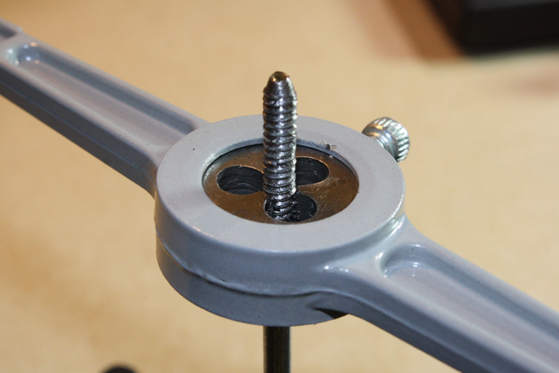
Figure 4-67. Completed thread cut with a 10-24 die
The die can exert a lot of force on the rod, so it needs to be firmly clamped vertically in a vise of some sort, as shown in Figure 4-67. It is not possible to reliably hold the work piece in your hand and cut threads into it with a die. As with tapping, be sure to use a lubricant to reduce friction and prevent binding. I used a light oil for the lubricant in this case. Figure 4-68 shows the finished rod with about 1 inch of threads cut into one end. A 10-24 nut has been threaded onto the rod as a check.
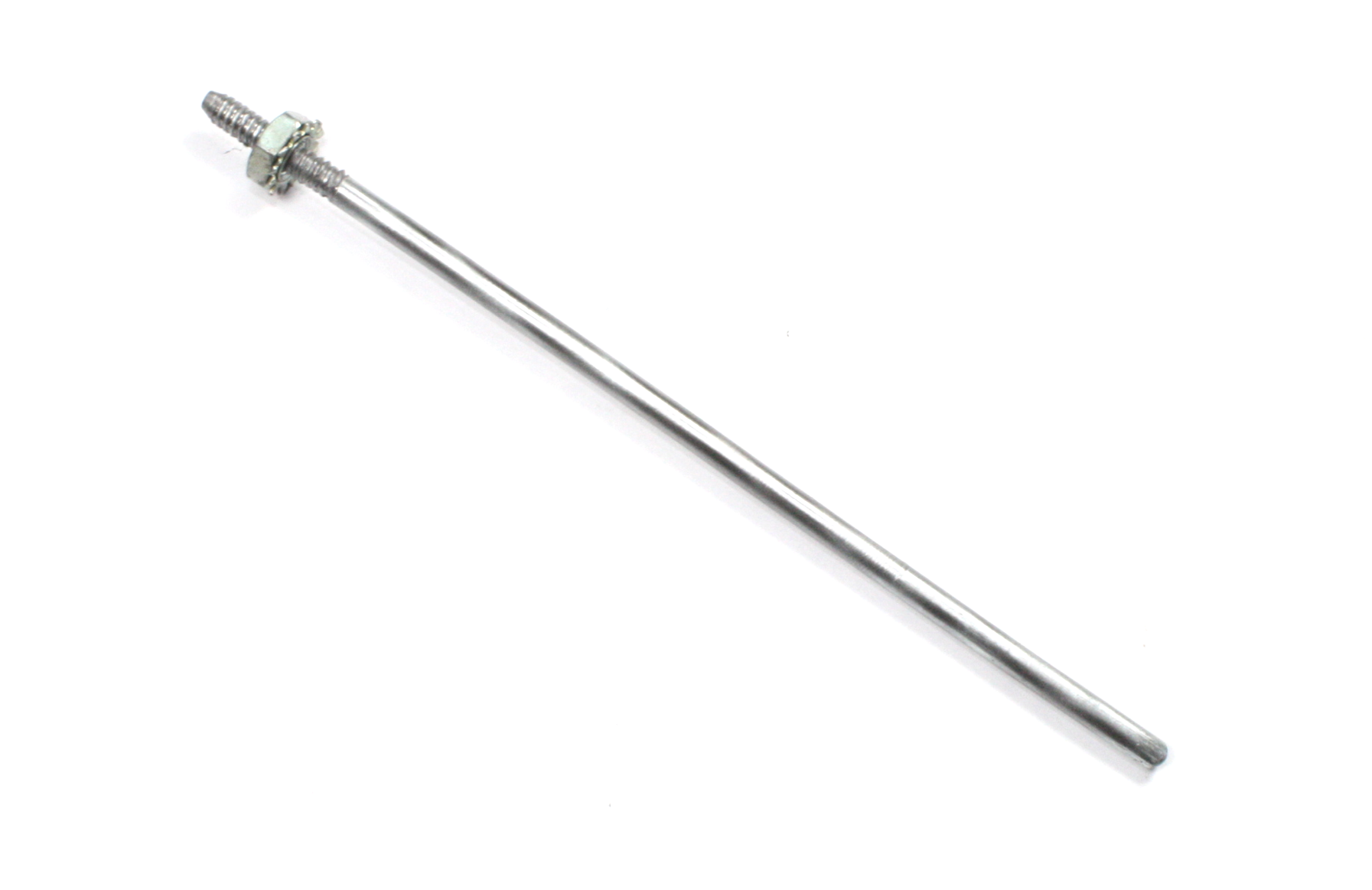
Figure 4-68. The finished rod with a 10-24 threaded section at one end
It is essential to always use a rod of the correct diameter for the threads you are trying to cut. Cutting an oversize rod with a die can result in the die becoming jammed onto the rod. If this happens, you might end up having to cut off the end of the rod, along with the jammed die, and then throwing it away. Forcing an oversized rod through a die can also dull or damage the die. Conversely, if the rod diameter is too small, the die’s teeth won’t cut deep enough threads and the threaded part probably won’t work correctly with a standard size threaded hole or nut.
Screws and bolts have two basic measurements that define the diameter of a part. The first is the thread diameter (or major diameter). This is the diameter of the outside of the threads on the part. The second is the root diameter (or minor diameter), which is the diameter of the part across the bottoms (valleys) of the threads.
In general, for UTS/ANSI threads, the thread (major) diameter of a particular gauge less about 0.005 inch works well as a rod diameter. Table 2-2 lists the thread diameters for common machine screws. Some tool manufacturers may offer diameter suggestions that are slightly different than the standard for a particular screw or bolt diameter, but the differences aren’t very much.
The dies found in an inexpensive kit are typically fixed in terms of the diameter of rod they will work with. Professional (and more expensive) tools have adjustments that allow the die to be sized. With these types of tools, one approach is to start off with the die opened up, and then bring it in to the final thread diameter over the course of multiple passes on the rod.
As stated earlier, cutting threads by hand with a die can be a major challenge. Perhaps the most challenging part is the amount of force needed to start the die while trying to keep it aligned at the same time. With a rod that has a diameter equivalent to the nut or threaded hole it will mate with, it can be really hard. Unless the part I’m making needs to be able to withstand significant stress, I typically use a rod with a diameter slightly less than what is listed in Table 2-2, just to make it easier on myself. If you find yourself cutting a lot of threads by hand, you may want to investigate the use of a small lathe or a special-purpose thread-cutting tool.
With both tap and die cutting, a general rule of thumb is that as the size (diameter) of the tap or die gets smaller, the harder it becomes to avoid breaking a tap, jamming a die, or twisting off the end of a rod with a die. Small-diameter screws and bolts typically have more threads per inch (or millimeter) than larger fasteners, and the threads are much finer. The result is that the tolerances are tighter and the chances for friction and binding much higher.
This section is just a cursory overview of the techniques used with taps and dies. This is an old subject, so there is a huge body of literature available. If you want to learn more, I would suggest investing in a machine shop reference book or two, such as Machinery’s Handbook (see Appendix C). Even older books (from the middle of the last century, for instance) have valuable information, and I’ve found some real gems on the bookshelves at thrift stores. Taps, dies, and drills haven’t changed much in the past 100 years, and neither have the techniques for using them.
Modification Cutting
Sometimes, you might need to cut something to modify it. For example, let’s say you want to modify a device to install a new module or component, but it won’t fit unless there’s a new hole for it to fit into. This is a case of hacking in the truest sense, and there are several ways to do it.
Jeweler’s Saw
A jeweler’s saw (introduced in “Small Hand Saws”) is designed to make small, precise cuts to create intricate patterns. Unlike a hacksaw, a jeweler’s saw uses a very narrow blade, which can be turned easily while cutting. A coping saw is similar to a jeweler’s saw but is used primarily in woodworking to create intricate patterns. Figure 4-69 shows a typical jeweler’s saw in action.
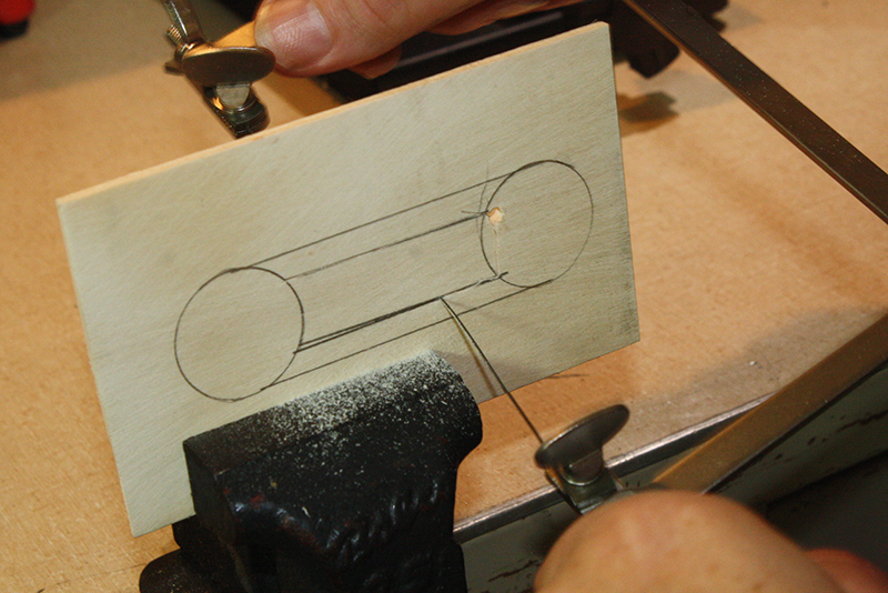
Figure 4-69. Using a jeweler’s saw
Using a jeweler’s saw takes a bit of practice. I recommend using guidelines, like the ones shown in Figure 4-69. The material is a piece of thin MDO (medium-density overlay, a type of plywood), but it could just as easily have been plastic or even thin sheet metal. The guidelines were made with a mechanical pencil. If you are cutting metal, you will probably want to use a fine-tip permanent marker (which comes off with rubbing alcohol, by the way).
The most common mistake is to apply too much force while trying to move the saw through the material to be cut. This usually results in a snapped blade. Let the saw do its job, and apply only enough pressure to keep it firmly in contact with the material. When turning a corner with a jeweler’s saw, move slowly and cut in short, even strokes. The objective is to avoid binding the blade in the turn while still staying on the guideline. Be patient; these little saws can do a good job, but they don’t do it very fast.
Note that the jeweler’s saw is being held with two hands in Figure 4-69. One hand provides the cutting force, while the other steadies the saw and guides it. While it is possible to operate a small saw like this one-handed, I don’t recommend it. It’s easy for the saw to “get away” from you and head off in a direction you don’t want it to go. Using two hands prevents this. You also need two hands to navigate corners.
I should also point out that the cut was started from the hole drilled to the inside of the circle on the right. The blade was removed from the far end of the saw frame, inserted through the hole, and then clamped back into the blade holder and retensioned. The near end of the blade (closest to the handle) was not removed. If you don’t want to have an entry cut coming in from the side of the piece you are cutting, there really isn’t any other way to do this. The blade is flexible and easy to remount once it is through the starting hole.
Rotary Tool
Modifying things is where a rotary tool really shines. Figure 4-70 shows a rotary tool with a cut-off disc attached. The cut-off disc is basically just a thin wafer of abrasive material made with a binding adhesive and formed under pressure, so it will wear down with use. If you are doing a lot of this type of cutting (or plan to), you might want to consider buying the cut-off discs in bulk packs.
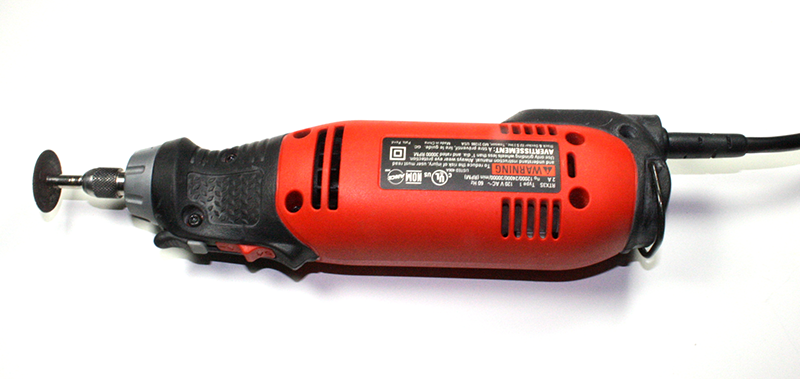
Figure 4-70. Rotary tool cut-off disc
It is a good idea to cut to the inside of the final dimensions of the hole, because holding a rotary tool steady while cutting can be a challenge. The edges of the hole can be finished out to the desired dimensions with a razor knife and a file, but a hole that is too large cannot be easily fixed.
You might find it difficult to hold the rotary tool steady while cutting a straight line. Here’s a trick to help with that: clamp the rotary tool down to the workbench, not the work piece you are cutting. A small bench vise, with some padding if necessary, works well for this, as shown in Figure 4-71.
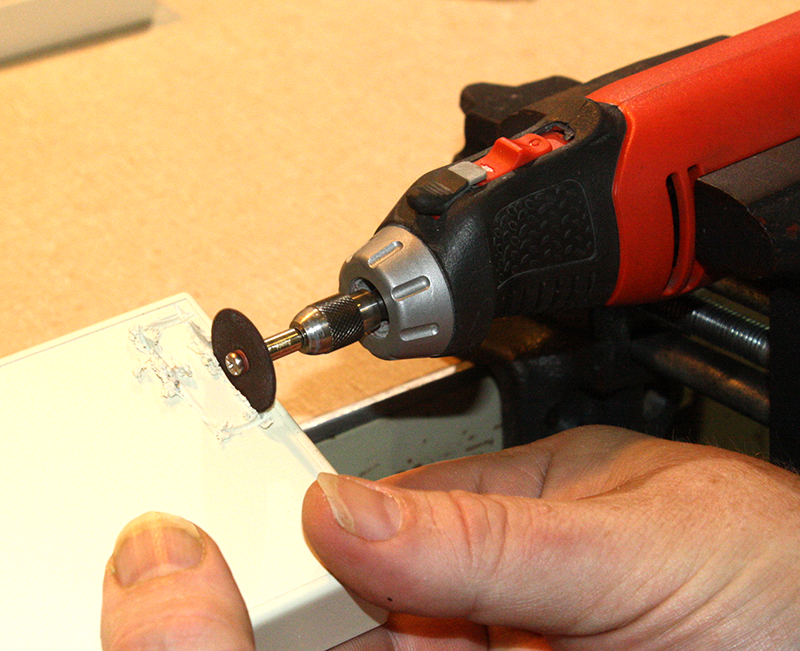
Figure 4-71. Rotary tool in a bench vise
Mounting the rotary tool in a vise allows you to move the piece you are cutting under the cutting wheel while the rotary tool is held firmly. The piece you are cutting is probably going to be much lighter and easier to maneuver than the tool. You can use something like a block of wood to brace your hand, or even support the work piece while cutting it. With a simple setup like this, you can get a much cleaner and straighter cut than when attempting to hold the tool in one hand and the work piece in the other.
Alternatively, you could use something like the X-Y cross-slide vise shown in Figure 4-72. In this case, I’ve used a cross-slide vise (it can be moved in the x and y axes) to hold the rotary tool. Once the tool and the piece to be cut are both clamped down, you can move the vise using the crank handles to produce a straight and clean cut. It is particularly useful for creating a clean notch in materials such as aluminum, which is what is being done in Figure 4-72. Widening the notch just requires a slight turn on one of the crank handles to shift the cutting blade over a small amount, and the other crank is used to move the cut-off disc through the material once more. Repeat as necessary to make a clean notch of the desired width.
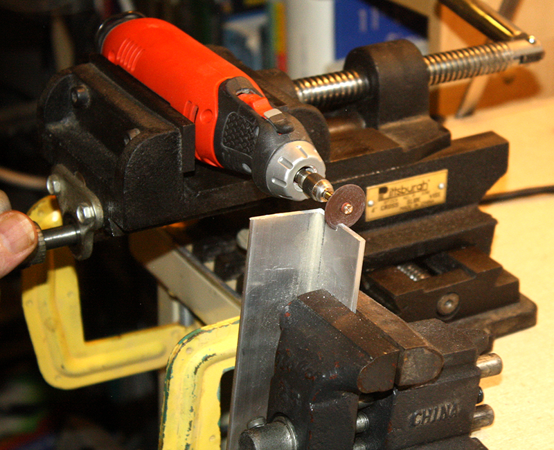
Figure 4-72. Holding a rotary tool in an X-Y cross-slide vise
A small bench vise (discussed in “Vises”) is holding the piece of aluminum to be cut. One downside to this setup is that there is no z-axis—in other words, no height adjustment. If the cut-off wheel of the rotary tool needs to move up or down relative to the work piece, then the work piece must be unclamped, adjusted, and then clamped back down again. But since this arrangement is primarily intended to make straight cuts through small items, it isn’t really that big of an inconvenience. If being able to move a cutting tool in three axes is a requirement, you can use something like a small milling machine.
A small file can be used to clean up the finished notch and level out the bottom of the cut. Since the abrasive wheel on the rotary tool wears down rather quickly, a notch made with multiple passes will tend to have a slope at the bottom. Alternatively, you could adjust the work piece to raise it slightly, and then repeat the cutting passes from the high end of the bottom of the notch back towards the original starting end. Some filing will still be necessary if you want a really clean and square cut.
If you’re curious as to what the cross-slide vise looks like, Figure 4-73 shows the model I happen to have. This is a 6-inch unit purchased from Harbor Freight for about $80 USD, and it does a fairly good job. For use with the rotary tool, I’ve used C clamps to hold it down, rather than bolting it directly to the workbench. This allows it to be moved if necessary, and it often ends up on the work table of a drill press. A handy thing to have; it gets around in the shop.
Figure 4-73. Cross-slide vise
Summary
In this chapter, we’ve covered a variety of tool techniques. There are, of course, more types of tools available than what we’ve seen here and in Chapter 3, but to do justice to them all would require a set of books rather than a couple of chapters. With what is here, you should be able to get a basic idea of how the various tools are used and what can be done with them, as well as what to watch out for when using them.
We’ve also seen that there is nothing wrong with modifying a tool so that it will perform better in a particular application. While it is possible to purchase sets of precision tools for special applications already shaped to specific widths and lengths, you can save a lot of money by doing it yourself if you are patient and have the right tools. The “right tools” in this case means a small grinder like the one shown in “Grinders”, and possibly a combination belt/disc sander. A vise also comes in handy for bending and shaping metal items, like tools, and there is also a small anvil in my shop for times when I need to beat on something to get it into the shape I want. (Or just when I feel like beating on something.)
An important point to take away from this chapter is that even though a tool might seem conceptually simple, there is often more to correctly using it than you might first think. The key is to gain experience with the various tools, research them to acquire additional details, and talk to people who have experience with them. Or, to summarize it another way: use the right tool for the job, and use the tool the way it was intended to be used.
One of the best ways to learn how to use tools correctly is to practice. This is one reason why this book mentions disassembling old electronic equipment in many different places. Another approach is to purchase practice kits made specifically to use as training aids. There are several sources for SMT soldering practice kits, which usually consist of a double-sided PCB with a selection of mounting patterns and some parts to solder. What the parts happen to be isn’t relevant, just the form factors. Try searching for “SMT practice kit” on Google to get some ideas of what is available and the typical cost.
Lastly, consider keeping a notebook for your own discoveries and thoughts regarding your tools and how you use them. While you probably don’t need to take notes on using a screwdriver, if you modify a screwdriver, it might be helpful to understand why you did so later on. This would apply to any tool customization that might not be intuitively obvious, and it definitely applies to special-purpose custom tools.
1 Photo by coronium, CC-BY-SA-3.0, http://bit.ly/cold-solder
2 Photo by coronium, CC-BY-SA-3.0, http://bit.ly/brokenjoints.
Get Practical Electronics: Components and Techniques now with the O’Reilly learning platform.
O’Reilly members experience books, live events, courses curated by job role, and more from O’Reilly and nearly 200 top publishers.

