1.3 Control of Power Converters and Drives
Control schemes for power converters and drives have been constantly evolving according to the development of new semiconductor devices and the introduction of new control platforms. While diode rectifiers operate without any control, analog control circuits were introduced for regulating the firing angle of thyristors. With the introduction of power transistors with faster switching frequencies, analog control circuits have been used from the beginning and later were replaced by digital control platforms with the possibility of implementing more advanced control schemes.
1.3.1 Power Converter Control in the Past
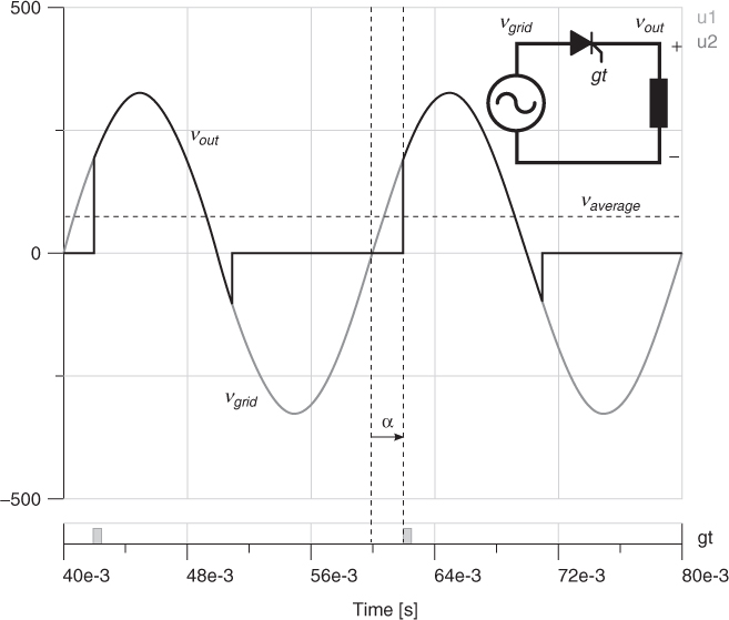
In thyristor-based rectifiers the average value of the output voltage can be adjusted by regulating the angle of the firing pulses in relation to the grid voltage. The control circuit for this power converter must detect the zero crossings of the grid voltage and generate the firing pulses according to the desired angle. Figure 1.4 shows the operation of a single-phase thyristor rectifier with a resistive–inductive load. It can be seen that the firing angle α modifies the waveform of the output voltage and, consequently, the average output voltage.
Figure 1.4 Operation of a single-phase thyristor rectifier

Thyristors switch at fundamental frequency, because their turn-off instant is line dependent and cannot be controlled. However, ...
Get Predictive Control of Power Converters and Electrical Drives now with the O’Reilly learning platform.
O’Reilly members experience books, live events, courses curated by job role, and more from O’Reilly and nearly 200 top publishers.

