4.4 Converter Model
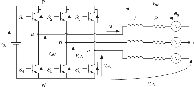
The power circuit of the three-phase inverter converts electrical power from DC to AC form using the electrical scheme shown in Figure 4.2. Considering that the two switches in each inverter phase operate in a complementary mode in order to avoid short-circuiting the DC source, the switching state of the power switches Sx, with x = 1, … , 6, can be represented by the switching signals Sa, Sb, and Sc defined as follows:
4.2 ![]()
4.3 ![]()
4.4 ![]()
Figure 4.2 Voltage source inverter power circuit
These switching signals define the value of the output voltages
4.6 ![]()
where Vdc is the DC source voltage.
Considering the unitary vector ![]() , which represents the 120° phase displacement ...
, which represents the 120° phase displacement ...
Get Predictive Control of Power Converters and Electrical Drives now with the O’Reilly learning platform.
O’Reilly members experience books, live events, courses curated by job role, and more from O’Reilly and nearly 200 top publishers.

