7.2 System Model
7.2.1 Matrix Converter Model
The power circuit of the MC is presented in Figure 7.1. It uses a set of bidirectional switches to directly connect the three-phase power supply to a three-phase load. This is a 3 × 3 MC. As shown in Figure 7.1, each bidirectional switch is composed of two power transistors with their parallel diodes in anti-series connection.
The MC is connected to the three-phase source through the input filter Lf, Rf, Cf. This filter has two main purposes:
Figure 7.1 Power circuit of the MC
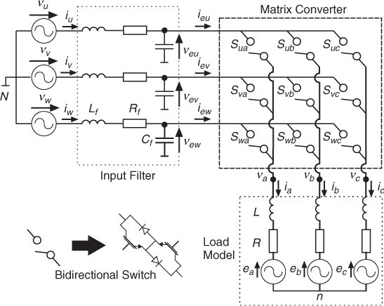
In Figure 7.1 each bidirectional switch is associated with a variable defined as Sxy with x ∈ {u, v, w} and y ∈ {a, b, c}. The conduction state of each bidirectional switch is determined exclusively by the value of its control signal. Sxy is also known as the switching function for switch xy. Sxy = 1 implies that switch xy is on, closed, or conducting, while Sxy = 0 means that the switch is off, open, or in blocking state.
It must be mentioned that the load current must not be interrupted abruptly, because the inductive nature of the load will generate an important overvoltage that can destroy the ...
Get Predictive Control of Power Converters and Electrical Drives now with the O’Reilly learning platform.
O’Reilly members experience books, live events, courses curated by job role, and more from O’Reilly and nearly 200 top publishers.

