12.2 Effect of Delay due to Calculation Time
The control of a three-phase inverter with a passive load (resistive–inductive) is used as an example application for explaining the effects of the delay due to calculation time and the delay compensation method. However, the same ideas are valid for all predictive control schemes.
The predictive current control scheme using MPC is shown in Figure 12.1 and consists of the following steps:
Figure 12.1 Predictive control scheme for a three-phase inverter
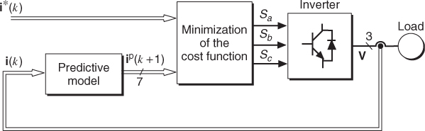
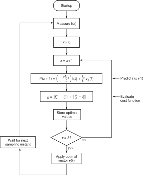
The predictive control algorithm can also be represented as the flowchart presented in Figure 12.2. As can be seen in this figure, calculation of the predicted current and cost function is repeated as many times as there are available switching states, leading to a large number of calculations performed by the microprocessor.
Figure 12.2 Flowchart of the predictive current control
In the case of current control, the cost function is defined as the error between the reference current ...
Get Predictive Control of Power Converters and Electrical Drives now with the O’Reilly learning platform.
O’Reilly members experience books, live events, courses curated by job role, and more from O’Reilly and nearly 200 top publishers.

