2.2 HIGH-PASS CIRCUITS
Figures 2.2(a) and 2.2(b) represent high-pass RC and RL circuits, respectively.
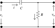
FIGURE 2.2(a) A high-pass RC circuit
Consider the high-pass RC circuit shown in Fig. 2.2(a). The capacitor offers a low reactance (XC = 1/jωC) as the frequency increases; hence, the output is large. Consequently, high-frequency signals are passed to the output with negligible attenuation whereas, at low frequencies, due to the large reactance offered by the condenser, the output signal is small. Similarly, in the circuit shown in Fig. 2.2(b), the inductive reactance XL (= jωL) increases with frequency, leading to a large output. At low frequencies, ...
Get Pulse and Digital Circuits now with the O’Reilly learning platform.
O’Reilly members experience books, live events, courses curated by job role, and more from O’Reilly and nearly 200 top publishers.

