7.2 COLLECTOR-COUPLED ASTABLE MULTIVIBRATORS
A collector-coupled astable multivibrator is shown in Fig. 7.1. Here, there is a cross-coupling from the second collector to the first base and also a cross-coupling from the first collector to the second base. This means that the output of one device is the input for the other. While analysing the functioning of this circuit, it is assumed that the circuit is an oscillator; and working backwards, we can justify that it does indeed oscillate.
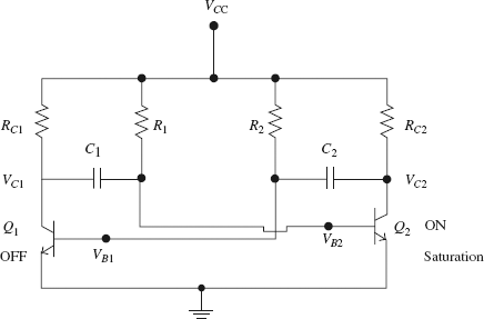
FIGURE 7.1 A collector-coupled astable multivibrator
Let us assume that at the given instant of time Q1 is OFF and Q2 is ON and saturated. Then VB2 = Vσ, V
Get Pulse and Digital Circuits now with the O’Reilly learning platform.
O’Reilly members experience books, live events, courses curated by job role, and more from O’Reilly and nearly 200 top publishers.

