Chapter 8. GPIO Basics
8.0. Introduction
This chapter contains some basic recipes for setting up and using the Raspberry Pi’s general-purpose input/output (GPIO) connector.
8.1. Finding Your Way Around the GPIO Connector
Note
Be sure to check out the accompanying video for this recipe at http://razzpisampler.oreilly.com.
Problem
You need to connect electronics to the GPIO connector, but you need to know more about what all the pins do.
Solution
Figure 8-1 shows the GPIO pinout for both revisions 1 and 2 of the Raspberry Pi Model B. The quick way to tell the boards apart is that if you have an older revision 1 board, it has a black audio socket. The revision 2 boards have a blue audio socket.
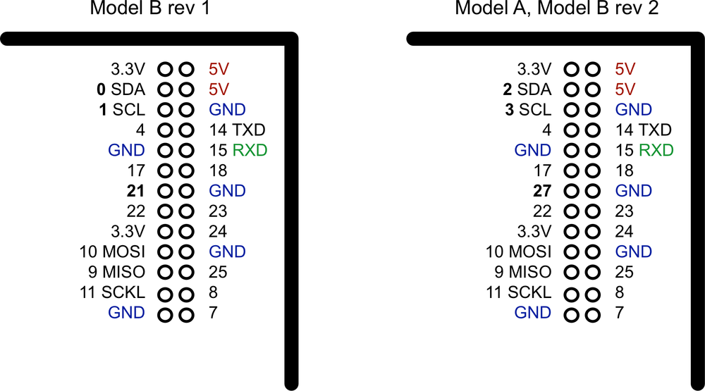
There were three changes to the GPIO connector between revision 1 and revision 2. These are highlighted in bold in Figure 8-1. First, the I2C port was swapped. The two pins SDA and SCL are still SDA and SCL but use a different internal I2C interface. This means that if you’re using the pins as GPIO rather than I2C, then you will refer to them as 2 and 3 on a revision 2 board. Also, GPIO 21 was replaced by GPIO 27 on revision 2.
At the top of the connector, there are 3.3V and 5V power supplies. The GPIO uses 3.3V for all inputs and outputs. Any pin with a number next to it can act as a GPIO pin. Those that have another name after them also have some other special purpose, so 14 ...
Get Raspberry Pi Cookbook now with the O’Reilly learning platform.
O’Reilly members experience books, live events, courses curated by job role, and more from O’Reilly and nearly 200 top publishers.

