3.3 Simulation Bench Overview
3.3.1 WiFi and WiMAX OFDM Transceiver Modeling
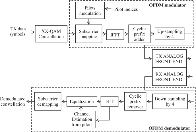
Figure 3.1 shows the block diagram of the OFDM transceiver simulator used to study the impact of the analog front-end imperfections on the system performance. All the simulations are performed using the baseband complex representation introduced and described in Section 1.4.4.
Figure 3.1 OFDM transceiver simulator

In transmission, random data symbols are generated and mapped to an XX-QAM complex constellation at the OFDM modulator input. The pilot-tones are modulated with fixed amplitude and phase. Afterwards, the pilot-tones and the data symbol constellations are mapped onto subcarriers in the frequency domain before applying an IFFT which generates the time-domain OFDM symbol. In the time domain a cyclic prefix is added to produce a guard interval between OFDM symbols, and finally an up-sampling by four delivers the digital signal to the transmit analog front-end DAC.
The receive path starts with the analog front-end which delivers the OFDM signal, digitized by an ADC, to the digital baseband. The down-sampling by four after the ADC is necessary to recover the IFFT/FFT sampling resolution imposed by the standard; after that the cyclic prefix is removed and an FFT is applied. Afterwards, channel estimation is performed from the pilot-tones in order to equalize the FFT output, especially to compensate ...
Get RF Analog Impairments Modeling for Communication Systems Simulation: Application to OFDM-based Transceivers now with the O’Reilly learning platform.
O’Reilly members experience books, live events, courses curated by job role, and more from O’Reilly and nearly 200 top publishers.

