August 2012
Intermediate to advanced
360 pages
10h 14m
English
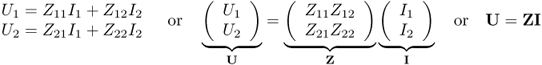
In circuit theory we use matrix equations to describe the electrical input-output behaviour (black-box description) of n-port networks, where n is the number of ports. The phasors of voltages Ui and currents Ii at the ports are related by a system of linear equations. To keep things simple at the beginning of our discussion we limit ourself to two-port networks. The results can easily be transferred to more than two ports.
Figure 5.1 shows a two-port network with voltage and current definition. At each port the sum of the currents is zero ![]() . Most often in general circuit theory we use the Z-parameter (impedance) matrix Z, the Y-parameter (admittance) matrix Y, the chain or ABCD-matrix A and the hybrid matrix H [1].
. Most often in general circuit theory we use the Z-parameter (impedance) matrix Z, the Y-parameter (admittance) matrix Y, the chain or ABCD-matrix A and the hybrid matrix H [1].
Figure 5.1 Definition of voltages and currents on a two-port network.

For the impedance matrix we write
The admittance matrix Y is given by
5.2 
The ABCD matrix is defined by
5.3 
The hybrid matrix takes the following form
5.4
Read now
Unlock full access