5.6 Signal Flow Method
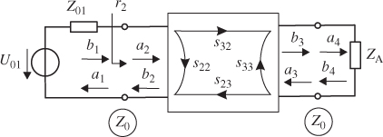
The scattering matrix S interrelates the incoming and outgoing normalized power waves ai and bi at all ports i of a network. If we interconnect several networks to form a circuit we can write down a set of equations that interrelate all power waves in that circuit. Figure 5.11 shows a circuit with an equivalent source, a two-port network and a load. By setting up and solving the resulting system of equations we derive the electrical behaviour of the circuit.
Figure 5.11 Calculation of RF circuits using power waves (two-port network with source and load).

As an alternative to the algebraic approach we can figure out the electrical behaviour by the signal flow method. This method represents a more direct and visual approach, especially when only simple feedback loops are involved. In the following we will discuss the basic rules and apply them to an illustrative example.
The signal flow method uses signal flow graphs to graphically represent scattering parameters and power waves. The scattering parameters are represented by arrows and the power waves are represented by nodes.
Signals that are passed along directed edges in the signal flow graph can be described by a set of rules given in Figure 5.12. The rules correlate signal flow graph and algebraic relation. The first three rules (directed, parallel and series connection) are intuitively clear. It is important ...