August 2012
Intermediate to advanced
360 pages
10h 14m
English
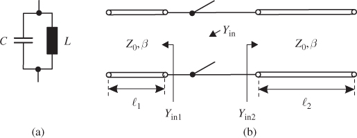
By using two concentrated elements (capacitor C and inductor L) we can design parallel and series resonance circuits. Figure 6.7a shows as an example a simple parallel-resonant circuit. The resonance frequency is given as
6.8 ![]()
At higher frequencies it is more difficult to use concentrated elements due to the parasitic effects discussed in the previous section. In RF engineering transmission lines become an interesting alternative. Therefore, we will look at the transmission line resonators that are important for the filters that will be discussed in later sections.
Figure 6.7 (a) LC resonator with lumped elements and (b) resonant circuit with half-wave transmission line (![]() =
= ![]() 1 +
1 + ![]() 2 = λ/2).
2 = λ/2).
Further resonating structures for filter design include the cavity resonators already discussed in Section 4.6.6. Oscillators (active circuits) employ quartzes and dielectric resonators. Further informations may be found in literature, for example [1–3].
Read now
Unlock full access


