6.7 Power Divider
6.7.1 Wilkinson Power Divider
In the previous section we considered a non-reciprocal, loss-less three-port network that was matched at all ports. Now we introduce a three-port network that is matched at all ports, reciprocal but lossy: a power divider.
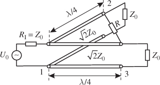
In Section 6.3.2 we looked at a simple power divider using two outgoing lines and a quarter-wave transformer for impedance matching at the input. The simple power divider was not matched at the output ports. With two quarter-wave transformers and a resistor R = 2Z0 we can design a power divider that is matched at all ports. Figure 6.34 shows the basic construction of a Wilkinson power divider.
Figure 6.34 Basic design of a Wilkinson power divider.

The power that is delivered to port 1 is split into equal parts and transferred to port 2 and port 3. Due to the symmetrical construction there is no voltage drop across the resistor R if the circuit is fed at port 1. Hence, there is no power loss in the resistor R. The resistor is only necessary to ensure the matching of port 2 and port 3.
The quarter-wave lines have characteristic impedances of ![]() and transform the output impedances Z0 to input impedances of 2Z0. The parallel circuit of the two quarter-wave transformers at the input terminal leads to Zin, 1 = (2Z0||2
and transform the output impedances Z0 to input impedances of 2Z0. The parallel circuit of the two quarter-wave transformers at the input terminal leads to Zin, 1 = (2Z0||2
Get RF and Microwave Engineering: Fundamentals of Wireless Communications now with the O’Reilly learning platform.
O’Reilly members experience books, live events, courses curated by job role, and more from O’Reilly and nearly 200 top publishers.

