Chapter 4. SDN Controllers
Introduction
The three most resonant concepts of SDN are programmability, the separation of the control and data planes, and the management of ephemeral network state in a centralized control model, regardless of the degree of centralization. Ultimately, these concepts are embodied in an idealized SDN framework, much as we describe in detail later in Chapter 9. The SDN controller is the embodiment of the idealized SDN framework, and in most cases, is a reflection of the framework.
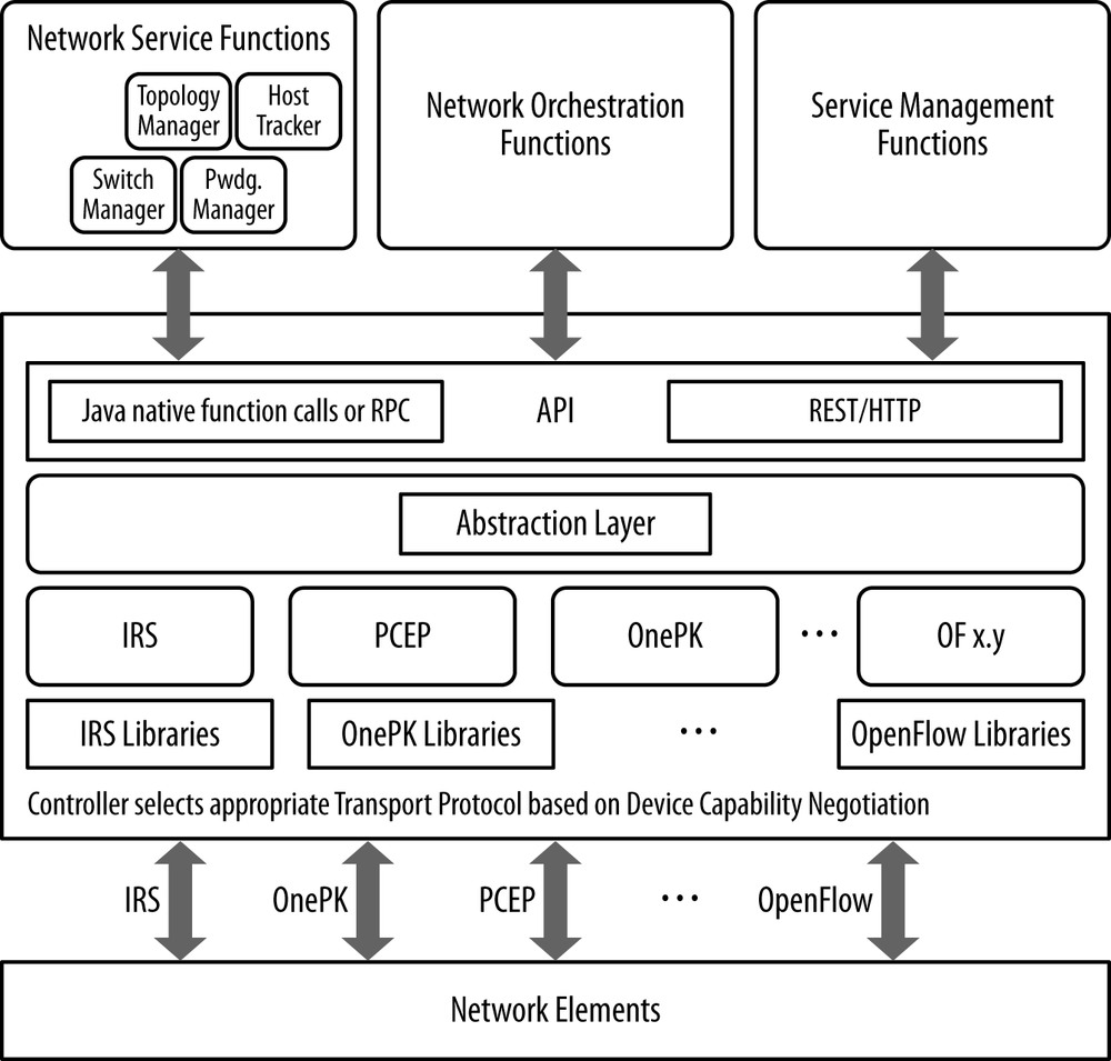
In theory, an SDN controller provides services that can realize a distributed control plane, as well as abet the concepts of ephemeral state management and centralization. In reality, any given instance of a controller will provide a slice or subset of this functionality, as well as its own take on these concepts. In this chapter, we will detail the most popular SDN controller offerings both from commercial vendors, as well as from the open source community. Throughout the chapter, we have included embedded graphics of the idealized controller/framework that was just mentioned as a means to compare and contrast the various implementations of controllers. We have also included text that compares the controller type in the text to that ideal vision of a controller.
Note
We would like to note that while it was our intention to be thorough in describing the most popular controllers, we likely missed a few. We also have detailed some commercial controller offerings, but likely missed some here too. Any of these omissions, if they exist, were not intentional, nor intended to indicate any preferences for one over the other.
General Concepts
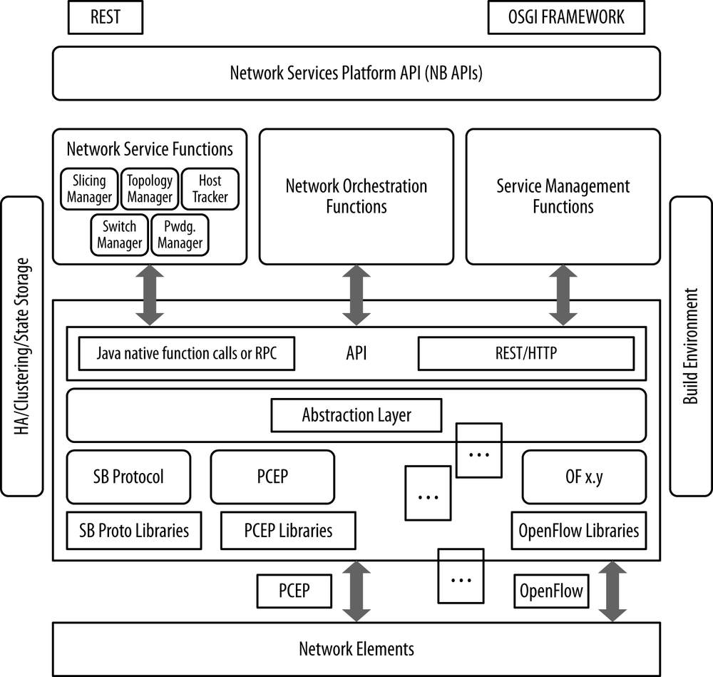
An idealized controller is shown in Figure 4-1, which is an illustration replicated from Chapter 9, but is repeated here for ease of reference. We will refer back to this figure throughout the chapter in an effort to compare and contrast the different controller offerings with each other.
The general description of an SDN controller is a software system or collection of systems that together provides:
Management of network state, and in some cases, the management and distribution of this state, may involve a database. These databases serve as a repository for information derived from the controlled network elements and related software as well as information controlled by SDN applications including network state, some ephemeral configuration information, learned topology, and control session information). In some cases, the controller may have multiple, purpose-driven data management processes (e.g., relational and nonrelational databases). In other cases, other in-memory database strategies can be employed, too.
A high-level data model that captures the relationships between managed resources, policies and other services provided by the controller. In many cases, these data models are built using the Yang modeling language.
A modern, often RESTful (representational state transfer) application programming interface (API) is provided that exposes the controller services to an application. This facilitates most of the controller-to-application interaction. This interface is ideally rendered from the data model that describes the services and features of the controller. In some cases, the controller and its API are part of a development environment that generates the API code from the model. Some systems go further and provide robust development environments that allow expansion of core capabilities and subsequent publishing of APIs for new modules, including those that support dynamic expansion of controller capabilities:
A secure TCP control session between controller and the associated agents in the network elements
A standards-based protocol for the provisioning of application-driven network state on network elements
A device, topology, and service discovery mechanism; a path computation system; and potentially other network-centric or resource-centric information services
The current landscape of controllers includes the commercial products of VMware (vCloud/vSphere), Nicira (NVP), NEC (Trema), Big Switch Networks (Floodlight/BNC), and Juniper/Contrail. It also includes a number of open source controllers.[60]
Besides the use of OpenFlow and proprietary protocols, there are SDN controllers that leverage IP/MPLS network functionality to create MPLS VPNs as a layer 3-over-layer 3 tenant separation model for data center or MPLS LSPs for overlays in the WAN.
We cannot ignore the assertions that NETCONF-based controllers[61] can almost be indistinguishable from network management solutions, or that Radius/Diameter-based controllers such as PCRF and/or TDF, in mobile environments, are also SDN controllers. This is true particularly as their southbound protocols become more independent and capable of creating ephemeral network/configuration state.
As we discussed earlier in this book, the original SDN application of data center orchestration spawned SDN controllers as part of an integrated solution. It was this use case that focused on the management of data center resources such as compute, storage, and virtual machine images, as well as network state. More recently, some SDN controllers began to emerge that specialized in the management of the network abstraction and were coupled with the resource management required in data centers through the support of open source APIs (OpenStack, Cloudstack). The driver for this second wave of controllers is the potential expansion of SDN applications out of the data center and into other areas of the network where the management of virtual resources like processing and storage does not have to be so tightly coupled in a solution.
The growth in the data center sector of networking has also introduced a great number of new network elements centered on the hypervisor switch/router/bridge construct. This includes the network service virtualization explored in a later chapter. Network service virtualization, sometimes referred to as Network Functions Virtualization (NFV), will add even more of these elements to the next generation network architecture, further emphasizing the need for a controller to operate and manage these things. We will also discuss the interconnection or chaining of NFV.
Virtual switches or routers represent a lowest common denominator in the networking environment and are generally capable of a smaller number of forwarding entries than their dedicated, hardware-focused brethren. Although they may technically be able to support large tables in a service VM, their real limits are in behaviors without the service VM. In particular, that is the integrated table scale and management capability within the hypervisor that is often implemented in dedicated hardware present only in purpose-built routers or switches. The simpler hypervisor-based forwarding construct doesn’t have room for the RIB/FIB combination present in a traditional purpose-built element. This is the case in the distributed control paradigm, which needs assistance to boil down the distributed network information to these few entries—either from a user-space agent that is constructed as part of the host build process and run as a service VM on the host, or from the SDN controller. In the latter case, this can be the SDN controller acting as a proxy in a distributed environment or as flow provisioning agent in an administratively dictated, centralized environment. In this way, the controller may front the management layer of a network, traditionally exposed by a network OSS.
For the software switches/routers on hosts in a data center, the SDN controller is a critical management interface. SDN controllers provide some management services (in addition to provisioning and discovery), since they are responsible for associated state for their ephemeral network entities (via the agent) like analytics and event notification. In this aspect, SDN has the potential to revolutionize our view of network element management (EMS).
VMware
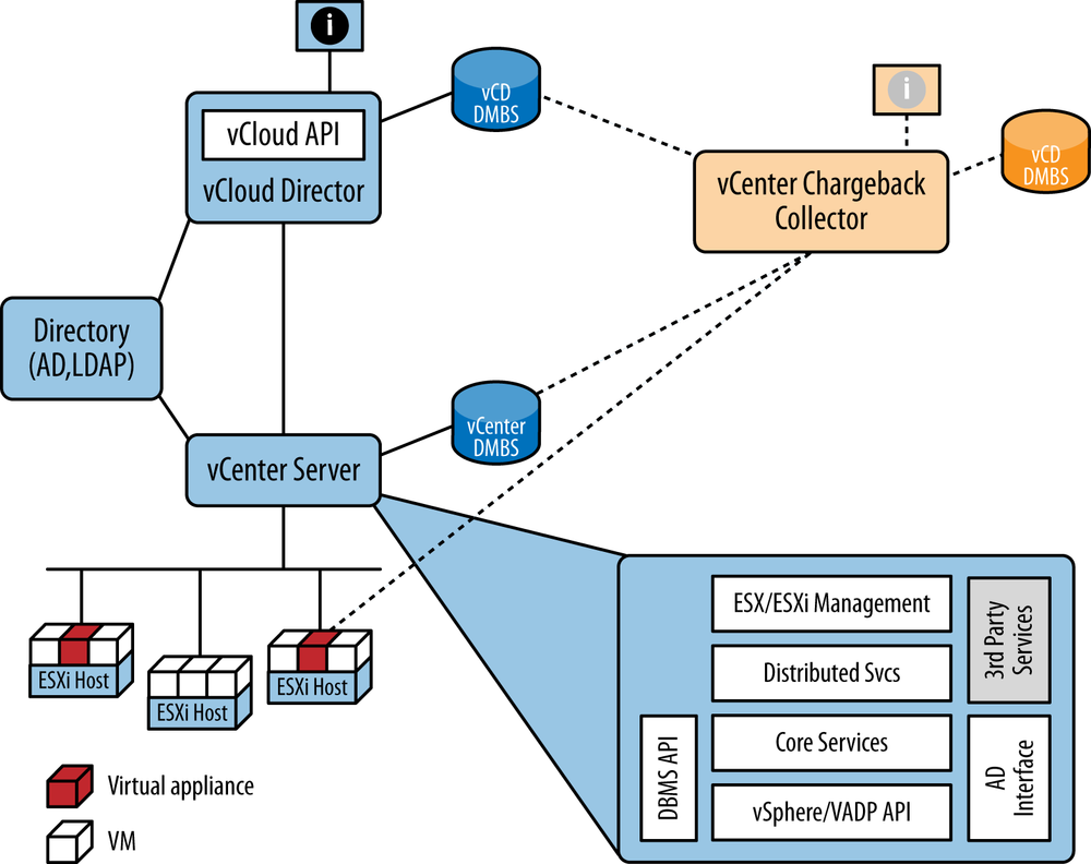
VMware provides a data center orchestration solution with a proprietary SDN controller and agent implementation that has become a de facto standard. VMware was one of the genesis companies for cloud computing, founded in 1998.[62] VMware provides a suite of data-center−centric applications built around the ESX (ESXi for version 5.0 and beyond) hypervisor (and hypervisor switch, the vSphere Distributed Switch [VDS]). See Figure 4-2 for a rough sketch of VMware product relationships.
vSphere introduced the ESXi hypervisor (with version 5.x) to replace the older ESX hypervisor, making it lighter/smaller (according to marketing pronouncements; ESXi is 5% of the size of ESX) and operating-system independent. The change also adds a web interface to the existing ESX management options of CLI, client API, and vCenter visualization. It also eliminated a required guest VM (i.e., guest VM per host) for a service console for local administration.
VDS is an abstraction (as a single logical switch) of what was previously a collection of individual virtual switches (vSphere Standard Switch/es) from a management perspective—allowing vCenter Server to act as a management/control point for all VDS instances (separating the management and data planes of individual VSSs).
Within VDS, VMware has abstractions of the physical card (vmnic), link properties (e.g., teaming, failover, and load balancing—dvuplink), and networking attributes (e.g., VLAN assignment, traffic shaping, and security de facto dvportgroup) that are used by the administrator as reusable configuration templates.
Once provisioned, the components necessary for network operation (the ESXi vswitch) will continue to operate even if the vCenter Server fails/partitions from the network.[63] Much of the HA scheme is managed within organizational clusters wherein a single agent is elected as master of a fault domain and the others are slaves. This creates a very scalable VM health-monitoring system that tolerates management communication partition by using heartbeats through shared data stores.
The aforementioned VMware applications are available in different bundles, exemplified by the vSphere/vCloud/vCenter Suite designed for IaaS applications, which includes:
- vSphere
Manages what is labeled “virtualized infrastructure” by VMware. This includes managing the hypervisor integrated vswitch (from a networking perspective) as well as the other, basic IaaS components—compute, storage, images, and services. The suite uses an SQL Database (Microsoft or Oracle) for resource data storage.
- vCloud Director and vCloud Connector
Primary application for compute, storage, image resource management, and public cloud extension.
- vCloud Networking and Security
Self-descriptive applications.
- vCloud Automation Center
Provisioning assist for IT management.
- vCenter Site Recovery Manager
A replication manager for automated disaster recovery.
- vCenter Operations Management Suite
Application monitoring, VM host and vSphere configuration and change management, discovery, charging, analytic, and alerting.
- vFabric Application Director for Provisioning
Application management (primarily for multitiered applications, described in the definition of degree of tenancy, and managing the dependencies).
In 2011, VMware launched an open source PaaS system called Cloud Foundry,[64] which offers a hosted service that runs on VMware.
The virtual switch in the hypervisor is programmed to create VxLAN tunnel overlays (encapsulating layer 2 in layer 3), creating isolated tenant networks. VMware interacts with its own virtual vswitch infrastructure through its own vSphere API and publishes a vendor-consumable API that allows third-party infrastructure (routers, switches, and appliances) to react to vCenter parameterized event triggers (e.g., mapping the trigger and its parameters to a vendor-specific configuration change).
One of the strengths of VMware vSphere is the development environment that allows third parties to develop hypervisor and/or user space service VM applications (e.g., firewalls, and anti-virus agents) that integrate via the vSphere API.
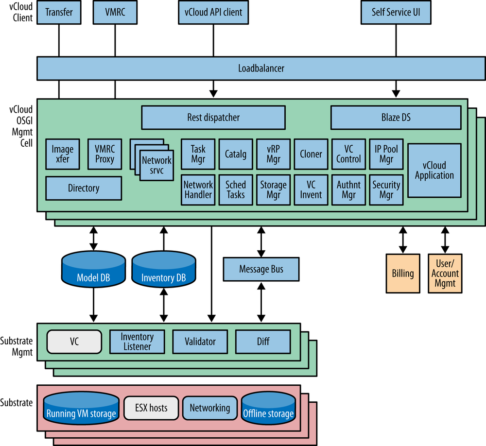
The core of VMware solution is Java-centric, with the following features:
HTTP REST-based API set oriented in expression toward the management of resources
Spring-based component framework[65]
Open Services Gateway Initiative (OSGI) module framework[66]
Publish/subscribe message bus based on JMS
Hibernate[67] DBMS interface (Hibernate is an object/relational mapping library that allows a Java developer to create/retrieve a relational store of objects).
The Spring development environment allows for the flexible creation and linking of objects (beans), declarative transaction and cache management and hooks to database services. Spring also provides for the creation of RESTful endpoints and thus an auto-API creation facility. Figure 4-3 shows the VMware/SpringSource relationship.
When looking over the architecture just described, one of the first things that might be apparent is the focus on integrated data center resource management (e.g., image, storage, and compute). From a controller standpoint, it’s important to note that the “controller” manages far more than just network state.
This is an important feature, as it can result in a unified and easy-to-operate solution; however, this approach has resulted in integration issues with other solution pieces such as data center switches, routers and appliances.
One of the primary detractions commonly cited with VMware is its cost.[68] This of course varies across customers, but open source offerings are (apparently) free by comparison. Even so-called enterprise versions of open source offerings are often less expensive than the equivalent offering. Other perhaps less immediately important considerations of this solution is its inherent scalability, which, like the price, is often something large-scale users complain about. The mapping and encapsulation data of the VxLAN overlay does not have a standardized control plane for state distribution, resulting in operations that resemble manual (or scripted) configuration and manipulation. Finally, the requirement to use multicast in the underlay to support flooding can be a problem, depending on what sort of underlay one deploys.
These points are not intended to imply that VMware has scaling problems, but rather that one of the facts of deploying commercial solutions is that you are more than likely going to have more than one server/controller, and the architecture has to either assume independence (i.e., a single monolith that operates as an autonomous unit) or support a federated model (i.e., clusters of servers working in conjunction to share state) in operation.
Nicira
Nicira was founded in 2007 and as such is considered a later arrival to the SDN marketplace than VMware. Nicira’s network virtualization platform (NVP) was released in 2011 and it is not the suite of resource management applications that comprises VMware; instead, it is more of a classic network controller, that is, where network is the resource managed. NVP now works in conjunction with the other cloud virtualization services for compute, storage, and image management.
NVP works with Open vSwitch (OVS).[69] OVS is the hypervisor softswitch controlled by the NVP controller cluster. This is good news because OVS is supported in just about every hypervisor[70] and is actually the basis of the switching in some commercial network hardware. As a further advantage, OVS is shipping as part of the Linux 3.3 build.
Until the relatively recent introduction of NXP, which is considered the first step in merging VMware and Nicira functionality, Nicira required a helper VM called Nicira OVS vApp for the VMware ESXi hypervisor in order to operate correctly. This vApp is mated to each ESXi hypervisor instance when the instance is deployed.
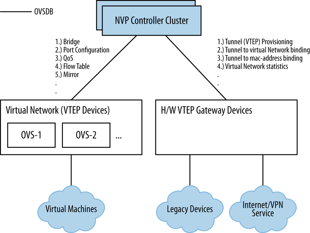
Though Nicira is a founding ONF member and its principals have backgrounds in the development of OpenFlow, Nicira only uses OpenFlow to a small degree. This is unlike a number of the other original SDN controller offerings. Most of the programming of OVS is achieved with a database-like protocol called the Open vSwitch Data Base Management Protocol (OVSDB).[71] OVSDB provides a stronger management interface to the hypervisor switch/element for programming tunnels, QoS, and other deeper management tasks for which OpenFlow had no capability when open vswitch was developed.
OVSDB characteristics include the following:
JSON used for schema format (OVSDB is schema-driven) and OVSDB wire protocol
Transactional
No-SQL
Persistency
Monitoring capability (alerting similar to pub-sub mechanisms)
Stores both provisioning and operational state
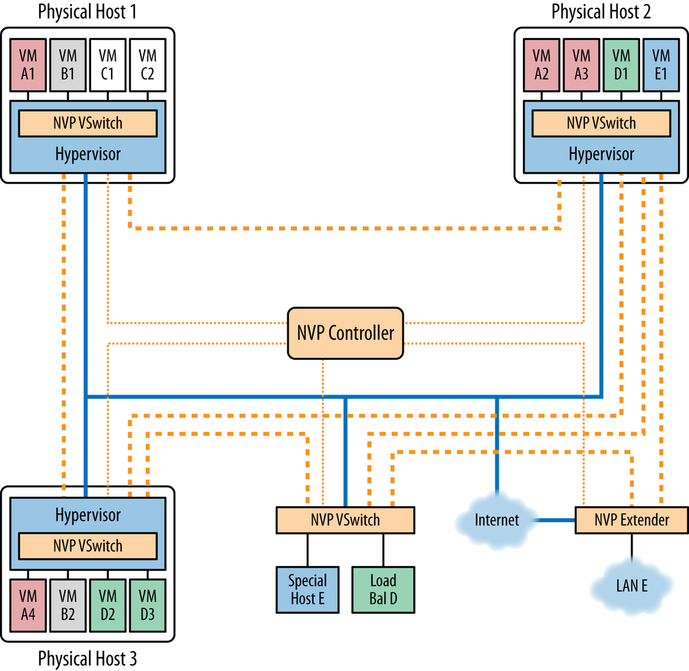
The Nicira NVP controller (Figure 4-4) is a cluster of generally three servers that use database synchronization to share state. Nicira has a service node concept that is used to offload various processes from the hypervisor nodes. Broadcast, multicast, and unknown unicast traffic flow are processed via the service node (IPSec tunnel termination happens here as well). This construct can also be used for inter-hypervisor traffic handling and as a termination point for inter-domain (or multidomain) inter-connect.
A layer 2 or layer 3 gateway product converts Nicira STT tunnel overlays into VLANs (layer 2), layer 2-to-layer 2 connectivity (VLAN to VLAN), or provides NAT-like functionality to advertise a tenant network (a private network address space) into a public address space. See Figure 4-5 for a sketch of the NVP component relationships.
OVS, the gateways, and the service nodes support redundant controller connections for high availability. NVP Manager is the management server with a basic web interface used mainly to troubleshoot and verify connections. The web UI essentially uses all the REST API calls on the backend for everything you do within it manually. For application developers, NVP offers a RESTful API interface, albeit a proprietary one.
Relationship to the idealized SDN framework
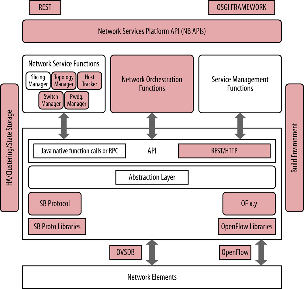
Figure 4-6 illustrates the relationship of the VMware/Nicira controller’s components to the idealized SDN framework. In particular, the Nicira controller provides a variety of RESTful northbound programmable APIs, network orchestration functions in the way of allowing a user to create a network overlay and link it to other management elements from vCenter/vCloudDirector, VxLAN, STT and OpenFlow southbound encapsulation capabilities, and OVSDB programmability in support of configuration of southbound OVS entities.
VMware/Nicira
Due to the acquisition of Nicira by VMware,[72] both of their products are now linked in discussion and in the marketplace. Though developed as separate products, they are merging[73] quickly into a seamless solution. Both Nicira and VMware products provide proprietary northbound application programming interfaces and use proprietary southbound interfaces/protocols that allow for direct interaction with network elements both real and virtual.
Nicira supports an OpenStack plug-in to broaden its capabilities in data center orchestration or resource management.
OpenFlow-Related
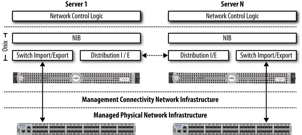
Most open source SDN controllers revolve around the OpenFlow protocol due to having roots in the Onix design (Figure 4-7),[74] while only some of the commercial products use the protocol exclusively. In fact, some use it in conjunction with other protocols.
Unlike the VMware/Nicira solution or the L3VPN/PCE solutions that follow, OpenFlow solutions don’t require any additional packet encapsulation or gateway. Although hybrid operation on some elements in the network will be required to interface OpenFlow and non-OpenFlow networks. This is in fact, growing to be a widely desired deployment model.
Unless otherwise stated, the open source OpenFlow controller solutions use memory resident or in-memory databases for state storage.
Relationship to the idealized SDN framework
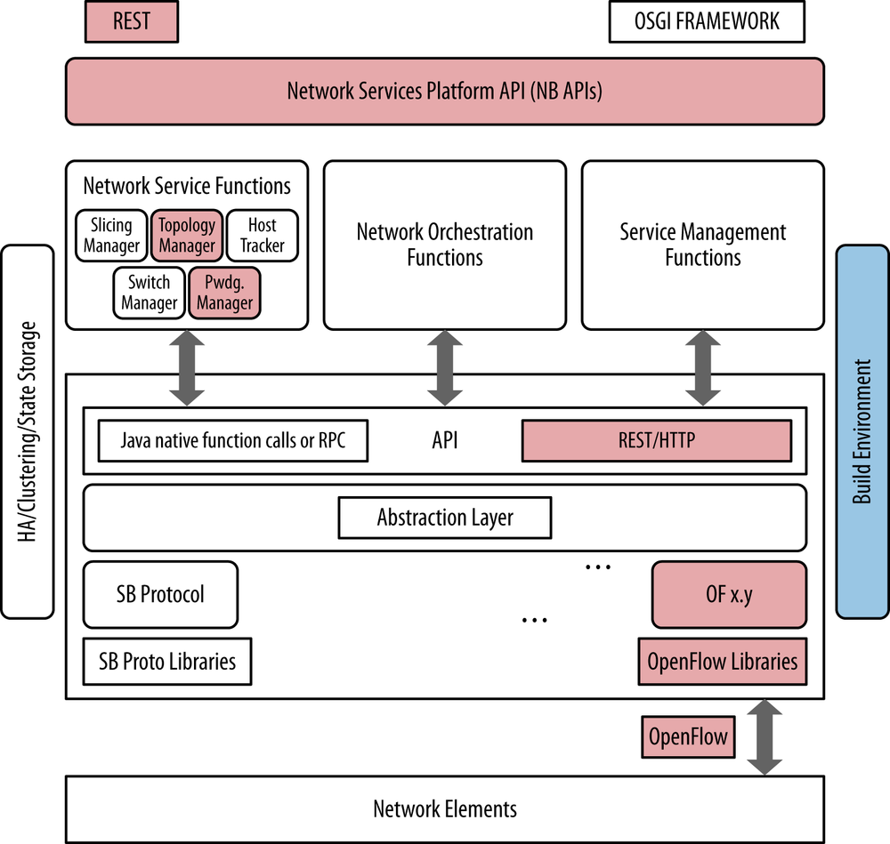
Figure 4-7 illustrates the relationship of, generally, any open source controller’s components to the idealized SDN framework. Since most controllers have been based on the Onix code and architecture, they all exhibit similar relationships to the idealized SDN framework. This is changing slowly as splinter projects evolve, but with the exception of the Floodlight controller that we will discuss later in the chapter, the premise that they all exhibit similar relationships still generally holds true.
The Onix controller model first relates to the idealized SDN framework in that it provides a variety of northbound RESTful interfaces. These can be used to program, interrogate, and configure the controller’s numerous functions, such as basic controller functionality, flow and forwarding entry programming, and topology. All of these controllers support some version of the OpenFlow protocol up to and including the latest 1.3 specification, as well as many extensions to the protocol in order to extend the basic capabilities of the protocol. Also note that while not called out directly, all Onix-based controllers utilize in-memory database concepts for state management. Figure 4-8 illustrates the relationship of the generalized open source OpenFlow controller’s components to the idealized SDN framework.
Mininet
Before introducing some of the popular Onix-based SDN controllers, we should take some time to describe Mininet, which is a network emulator that simulates a collection of end-hosts, switches, routers, and links on a single Linux kernel. Each of these elements is referred to as a “host.” It uses lightweight virtualization to make a single system look like a complete network, running the same kernel, system, and user code. Mininet is important to the open source SDN community as it is commonly used as a simulation, verification, testing tool, and resource. Mininet is an open source project hosted on GitHub. If you are interested in checking out the freely available source code, scripts, and documentation, refer to GitHub.
A Mininet host behaves just like an actual real machine and generally runs the same code—or at least can. In this way, a Mininet host represents a shell of a machine that arbitrary programs can be plugged into and run. These custom programs can send, receive, and process packets through what to the program appears to be a real Ethernet but is actually a virtual switch/interface. Packets are processed by virtual switches, which to the Mininet hosts appear to be a real Ethernet switch or router, depending on how they are configured. In fact, commercial versions of Mininet switches such as from Cisco and others are available that fairly accurately emulate key switch characteristics of their commercial, purpose-built switches such as queue depth, processing discipline, and policing processing. One very cool side effect of this approach is that the measured performance of a Mininet-hosted network often should approach that of actual (non-emulated) switches, routers, and hosts.
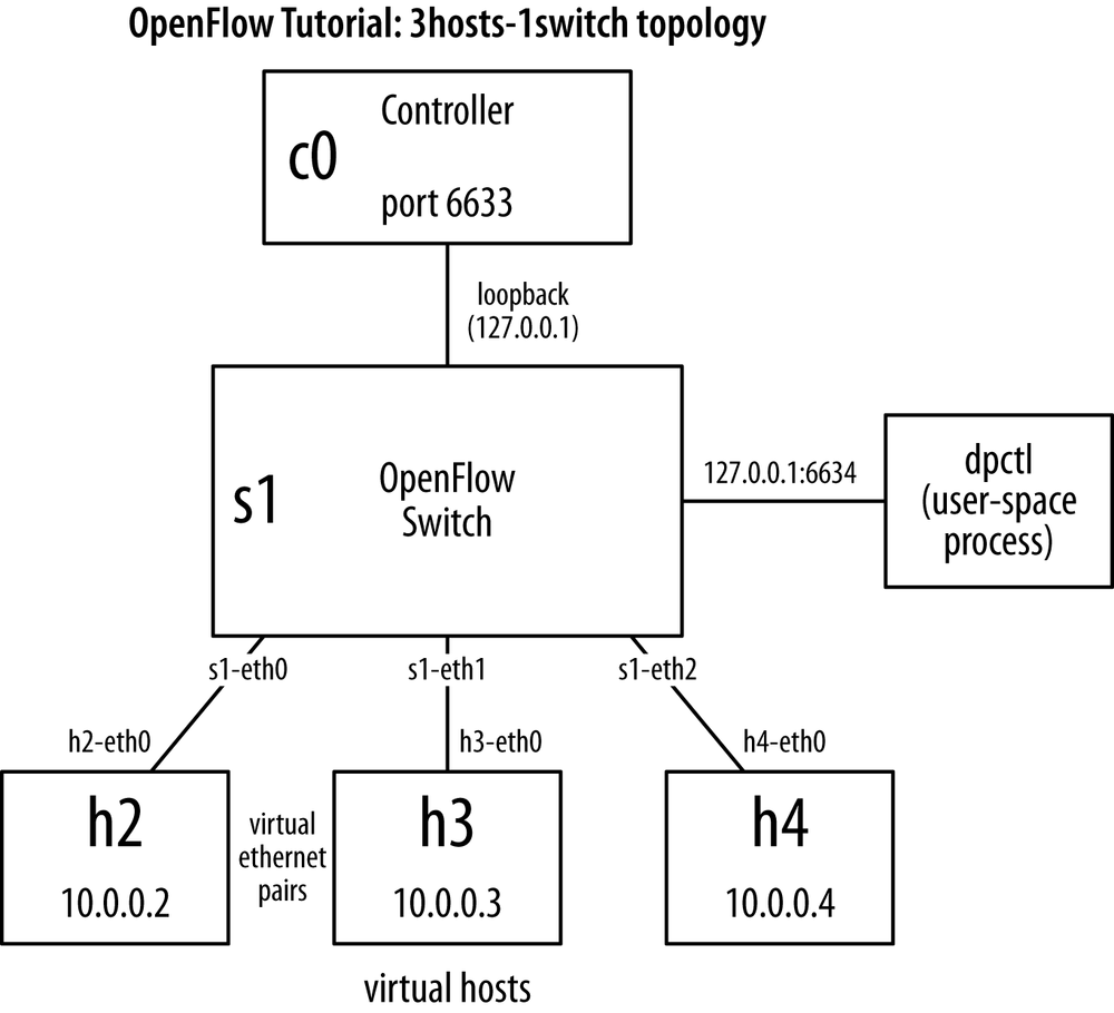
Figure 4-9 illustates a simple Mininet network comprised of three hosts, a virtual OpenFlow switch, and an OpenFlow controller. All components are connected over virtual Ethernet links that are then assigned private net-10 IP addresses for reachability. As mentioned, Mininet supports very complex topologies of nearly arbitrary size and ordering, so one could, for example, copy and paste the switch and its attached hosts in the configuration, rename them, and attach the new switch to the existing one, and quickly have a network comprised of two switches and six hosts, and so on.
One reason Mininet is widely used for experimentation is that it allows you to create custom topologies, many of which have been demonstrated as being quite complex and realistic, such as larger, Internet-like topologies that can be used for BGP research. Another cool feature of Mininet is that it allows for the full customization of packet forwarding. As mentioned, many examples exist of host programs that approximate commercially available switches. In addition to those, some new and innovative experiments have been performed using hosts that are programmable using the OpenFlow protocol. It is these that have been used with the Onix-based controllers we will now discuss.
NOX/POX
According to the NOX/POX website,[75] NOX[76] was developed by Nicira and donated to the research community and hence becoming open source in 2008. This move in fact made it one of the first open source OpenFlow controllers. It was subsequently extended and supported via ON.LAB[77] activity at Stanford University with major contributions from UC Berkeley and ICSI. NOX provides a C++ API to OpenFlow (OF v1.0) and an asynchronous, event-based programming model.
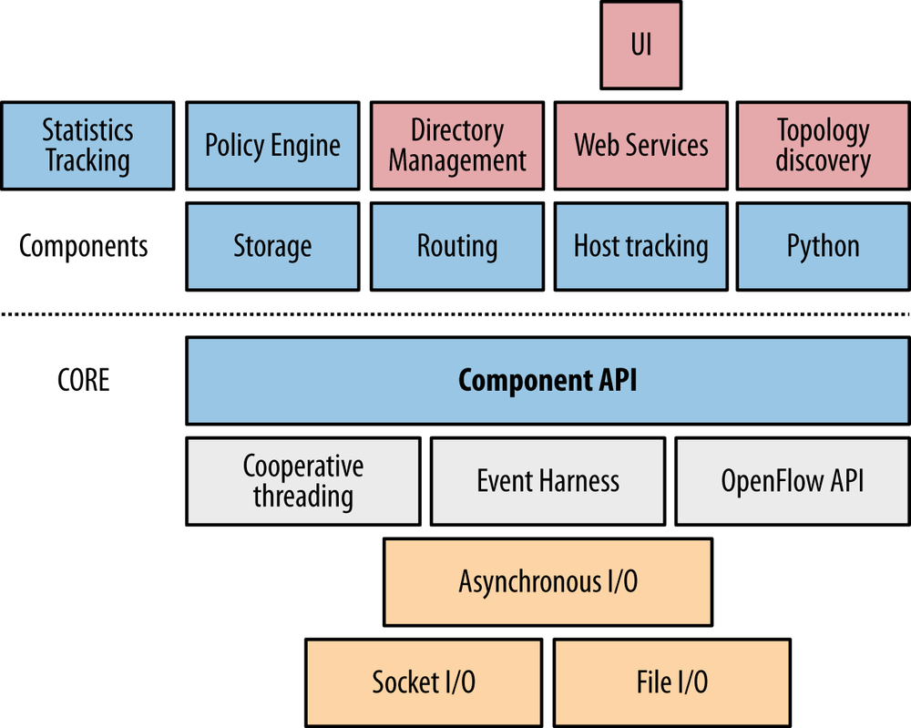
NOX is both a primordial controller and a component-based framework for developing SDN applications. It provides support modules specific to OpenFlow but can and has been extended. The NOX core provides helper methods and APIs for interacting with OpenFlow switches, including a connection handler and event engine. Additional components that leverage that API are available, including host tracking, routing, topology (LLDP), and a Python interface implemented as a wrapper for the component API, as shown in Figure 4-10.
NOX is often used in academic network research to develop SDN applications such as network protocol research. One really cool side effect of its widespread academic use is that example code is available for emulating a learning switch and a network-wide switch, which can be used as starter code for various programming projects and experimentation.
Some popular NOX applications are SANE and Ethane. SANE is an approach to representing the network as a filesystem. Ethane is a Stanford University research application for centralized, network-wide security at the level of a traditional access control list. Both demonstrated the efficiency of SDN by reducing the lines of code required significantly[78] to implement these functions that took significantly more code to implement similar functions in the past. Based on this success, researchers have been demonstrating MPLS-like applications on top of a NOX core.
POX is the newer, Python-based version of NOX (or NOX in Python). The idea behind its development was to return NOX to its C++ roots[79] and develop a separate Python-based platform (Python 2.7). It has a high-level SDN API including a query-able topology graph and support for virtualization.
POX claims the following advantages over NOX:
POX has a Pythonic OpenFlow interface.
POX has reusable sample components for path selection, topology discovery, and so on.
POX runs anywhere and can be bundled with install-free PyPy runtime for easy deployment.
POX specifically targets Linux, Mac OS, and Windows.
POX supports the same GUI and visualization tools as NOX.
POX performs well compared to NOX applications written in Python.
NOX and POX currently communicate with OpenFlow v1.0 switches and include special support for Open vSwitch.
Trema
Trema[80] is an OpenFlow programming framework for developing an OpenFlow controller that was originally developed (and supported) by NEC with subsequent open source contributions (under a GPLv2 scheme).
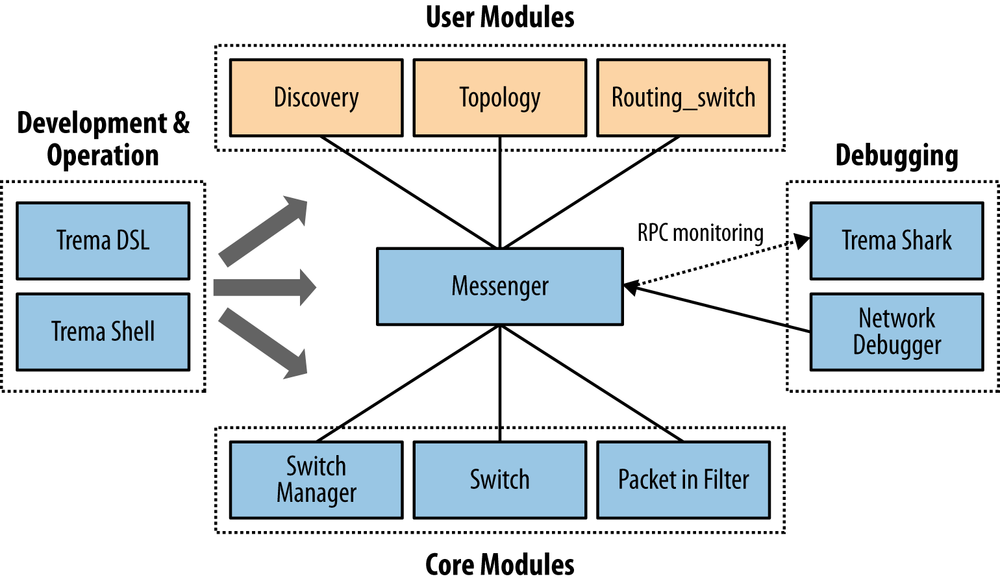
Unlike the more conventional OpenFlow-centric controllers that preceded it, the Trema model provides basic infrastructure services as part of its core modules that support (in turn) the development of user modules (Trema apps[81]). Developers can create their user modules in Ruby or C (the latter is recommended when speed of execution becomes a concern).
The main API the Trema core modules provide to an application is a simple, non-abstracted OpenFlow driver (an interface to handle all OpenFlow messages). Trema now supports OpenFlow version 1.3.X via a repository called TremaEdge.[82]
Trema does not offer a NETCONF driver that would enable support of of-config.
In essence, a Trema OpenFlow Controller is an extensible set of Ruby scripts. Developers can individualize or enhance the base controller functionality (class object) by defining their own controller subclass object and embellishing it with additional message handlers.
The base controller design is event-driven (dispatch via retrospection/naming convention) and is often (favorably by Trema advocates) compared to the explicit handler dispatch paradigm of other open source products.
In addition, the core modules provide a message bus (IPC mechanism via Messenger) that allows the applications/user_modules to communicate with each other and core modules (originally in a point-to-point fashion, but migrating to a publish/subscribe model), as shown in Figure 4-11.
Other core modules include timer and logging libraries, a packet parser library, and hash-table and linked-list structure libraries.
The Trema core does not provide any state management or database storage structure (these are contained in the Trema apps and could be a default of memory-only storage using the data structure libraries).[83]
The infrastructure provides a command-line interface (CLI) and configuration filesystem for configuring and controlling applications (resolving dependencies at load-time), managing messaging and filters, and configuring virtual networks—via Network Domain Specific Language (DSL, a Trema-specific configuration language).
The appeal of Trema is that it is an all-in-one, simple, modular, rapid prototype and development environment that yields results with a smaller codebase. The development environment also includes network/host emulators and debugging tools (integrated unit testing, packet generation/Tremashark/Wireshark).[84] The Trema applications/user_modules include a topology discovery/management unit (libtopology), a Flow/Path management module (libpath), a load balancing switch module and a sliceable switch abstraction (that allows the management of multiple OpenFlow switches). There is also an OpenStack Quantum plug-in available for the sliceable switch abstraction.[85]
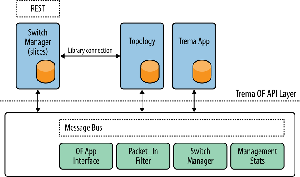
A Trema-based OpenFlow controller can interoperate with any element agent that supports OpenFlow (OF version compatibility aside) and doesn’t require a specific agent, though one of the apps developed for Trema is a software OpenFlow switch (positioned in various presentations as simpler than OVS). Figure 4-12 illustrates the Trema architecture.
The individual user modules (Trema applications) publish RESTful interfaces. The combination of modularity and per-module (or per-application service) APIs, make Trema more than a typical controller (with a monolithic API for all its services). Trema literature refers to Trema as a framework. This idea is expanded upon in a later chapter.
Ryu
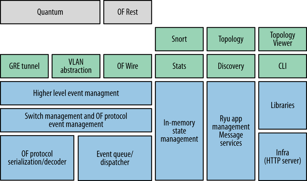
Ryu[86] is a component-based, open source (supported by NTT Labs) framework implemented entirely in Python (Figure 4-13). The Ryu messaging service does support components developed in other languages.
Components include an OpenFlow wire protocol support (up through version 1.3 of OF-wire including Nicira extensions), event management, messaging, in-memory state management, application management, infrastructure services and a series of reusable libraries (e.g., NETCONF library, sFlow/Netflow library).
Additionally, applications like Snort, a layer 2 switch, GRE tunnel abstractions, VRRP, as well as services (e.g., topology and statistics) are available.
At the API layer, Ryu has an Openstack Quantum plug-in that supports both GRE based overlay and VLAN configurations.
Ryu also supports a REST interface to its OpenFlow operations.
A prototype component has been demonstrated that uses HBase for statistics storage, including visualization and analysis via the stats component tools.
While Ryu supports high availability via a Zookeeper component, it does not yet support a cooperative cluster of controllers.
Big Switch Networks/Floodlight
Floodlight[87] is a very popular SDN controller contribution from Big Switch Networks to the open source community. Floodlight is based on Beacon from Stanford University. Floodlight is an Apache-licensed, Java-based OpenFlow controller (non-OSGI). The architecture of Floodlight as well as the API interface is shared with Big Switch Network’s commercial enterprise offering Big Network Controller (BNC).[88]
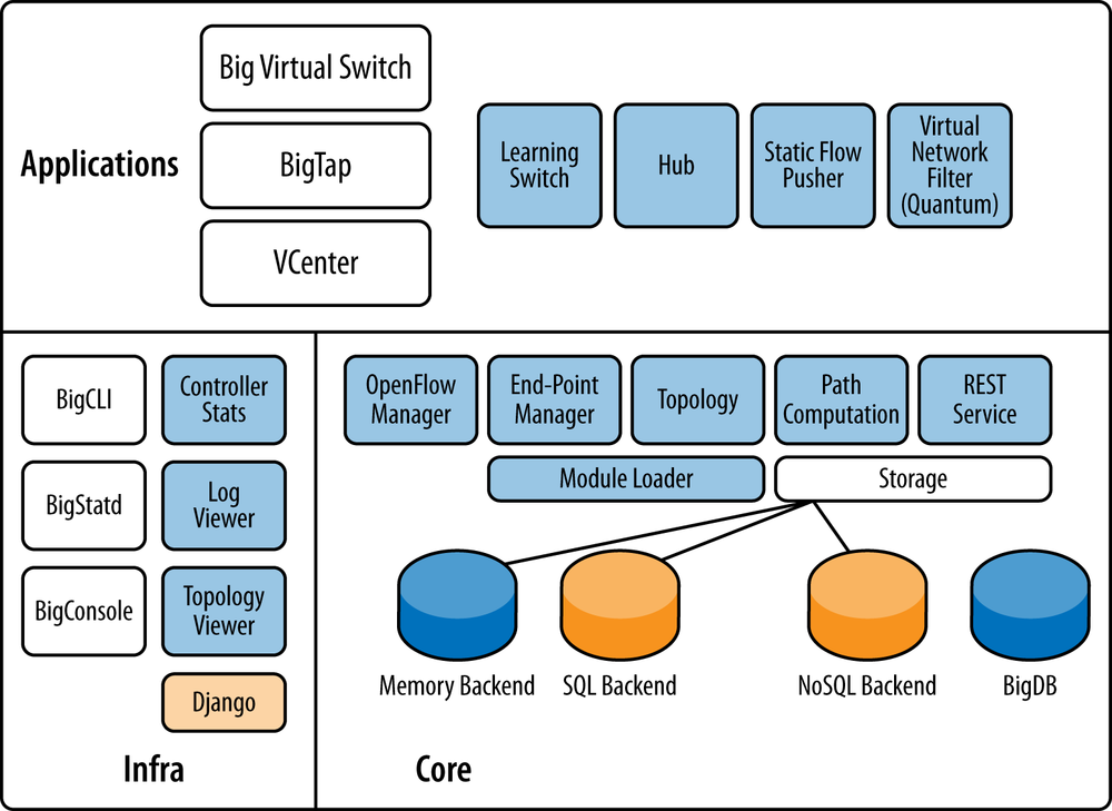
The Floodlight core architecture is modular, with components including topology management, device management (MAC and IP tracking), path computation, infrastructure for web access (management), counter store (OpenFlow counters), and a generalized storage abstraction for state storage (defaulted to memory at first, but developed into both SQL and NoSQL backend storage abstractions for a third-party open source storage solution).
These components are treated as loadable services with interfaces that export state. The controller itself presents a set of extensible REST APIs as well as an event notification system. The API allows applications to get and set this state of the controller, as well as to subscribe to events emitted from the controller using Java Event Listeners, as shown in Figure 4-14.[89] These are all made available to the application developer in the typical ways.[90]
The core module called the Floodlight Provider, handles I/O from switches and translates OpenFlow messages into Floodlight events, thus creating an event-driven, asynchronous application framework. Floodlight incorporates a threading model that allows modules to share threads with other modules. Event handling within this structure happens within the publishing module’s thread context. Synchronized locks protect shared data. Component dependencies are resolved at load-time via configuration.
The topology manager uses LLDP (as does most OpenFlow switches) for the discovery of both OpenFlow and non-OF endpoints.
There are also sample applications that include a learning switch (this is the OpenFlow switch abstraction most developers customize or use in its native state), a hub application, and a static flow push application.
In addition, Floodlight offers an OpenStack Quantum plug-in.
The Floodlight OpenFlow controller can interoperate with any element agent that supports OpenFlow (OF version compatibility aside, at the time of writing, support for both of-config and version 1.3 of the wire protocol were roadmap items), but Big Switch also provides an open source agent (Indigo[91]) that has been incorporated into commercial products. In addition, Big Switch has also provided Loxi, an open source OpenFlow library generator, with multiple language support[92] to address the problems of multiversion support in OpenFlow.
As a development environment, Floodlight is Java/Jython centric. A rich development tool chain of build and debugging tools is available, including a packet streamer and the aforementioned static flow pusher. In addition, Mininet[93] can be used to do network emulation, as we described earlier.
Because the architecture uses restlets,[94] any module developed in this environment can expose further REST APIs through an IRestAPI service. Big Switch has been actively working on a data model compilation tool that converted Yang to REST, as an enhancement to the environment for both API publishing and data sharing. These enhancements can be used for a variety of new functions absent in the current controller, including state and configuration management.
Relationship to the idealized SDN framework
As we mentioned in the previous section, Floodlight is related to the base Onix controller code in many ways and thus possesses many architectural similarities. As mentioned earlier, most Onix-based controllers utilize in-memory database concepts for state management, but Floodlight is the exception. Floodlight is the one Onix-based controller today that offers a component called BigDB. BigDB is a NoSQL, Cassandra-based database that is used for storing a variety of things, including configuration and element state.
When we look at the commercial superset of Floodlight (BNC) and its applications, its coverage in comparison with the idealized controller rivals that of the VMware/Nicira combination (in Figure 4-5). The combination supports a single, non-proprietary southbound controller/agent (OpenFlow).
Layer 3 Centric
Controllers supporting L3VPN overlays such as Juniper Networks Contrail Systems Controller, and L2VPN overlays such as Alcatel Lucent’s Nuage Controller[95] are coming to market that promote a virtual Provider Edge (vPE) concept. The virtualization of the PE function is an SDN application in its own right that creates both service or platform virtualization. The addition of a controller construct aids in the automation of service provisioning as well as providing centralized label distribution and other benefits that may ease the control protocol burden on the virtualized PE.
There are also path computation engine (PCE) servers that are emerging as a potential controllers or as enhancements to existing controllers for creating MPLS LSP overlays in MPLS-enabled networks. These can be used to enable overlay abstractions and source/destination routing in IP networks using MPLS labels without the need for the traditional label distribution and tunnel/path signaling protocols such as LDP and RSVP-TE.
L3VPN
The idea behind these offerings is that a VRF structure (familiar in L3VPN) can represent a tenant and that the traditional tooling for L3VPNs (with some twists) can be used to create overlays that use MPLS labels for the customer separation on the host, service elements, and data center gateways.
This solution has the added advantage of potentially being theoretically easier to stitch into existing customer VPNs at data center gateways—creating a convenient cloud bursting application. This leverages the strength of the solution—that state of the network primitives used to implement the VRF/tenant is carried in standard BGP address families.
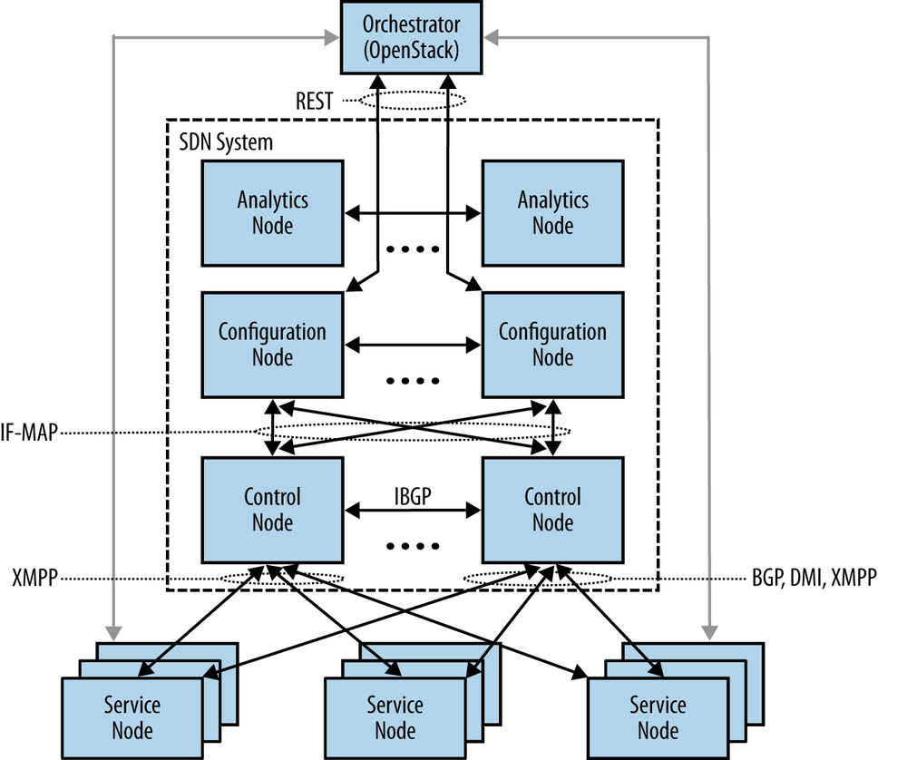
In the case of Juniper Networks, which acquired its SDN controller technology from Contrail Systems, the offering involves a controller that appears to be a virtualized route reflector that supports an OpenStack API mapping to its internal service creation APIs. The Juniper approach involves a high-level data model (originally envisioned to be IF-MAP[96] based) that self-generates and presents a REST API to SDN applications such as the one shown in Figure 4-15. The figure demonstrates a data center orchestration application that can be used to provision virtual routers on hosts to bind together the overlay instances across the network underlay. A subset of the API overlaps the OpenStack Quantum API and is used to orchestrate the entire system.
The controller is a multi-Node design comprised of multiple subsystems. The motivation for this approach is to facilitate scalability, extensibility, and high availability. The system supports potentially separable modules that can operate as individual virtual machines in order to handle scale out server modules for analytics, configuration, and control. As a brief simplification:
- Analytics
Provides the query interface and storage interface for statistics/counter reporting
- Configuration
Provides the compiler that uses the high-level data model to convert API requests for network actions into low-level data model for implementation via the control code
- Control
The BGP speaker for horizontal scale distribution between controllers (or administrative domains) and the implementer of the low-level data model (L3VPN network primitives distributed via XMPP commands—VRFs, routes, policies/filters). This server also collects statistics and other management information from the agents it manages via the XMPP channel.
The Control Node uses BGP to distribute network state, presenting a standardized protocol for horizontal scalability and the potential of multivendor interoperability. However, it’s more useful in the short term for interoperability with existing BGP networks. The architecture synthesizes experiences from more recent, public architecture projects for handling large and volatile data stores and modular component communication.
The Contrail solution leverages open source solutions internal to the system that are proven. For example, for analytics data, most operational data, and the IF-MAP data store, Cassandra[97] was incorporated. Redis[98] was employed as a pub-sub capable messaging system between components/applications. It should be noted that Redis was originally sponsored by VMware. Zookeeper[99] is used in the discovery and management of elements via their agents.
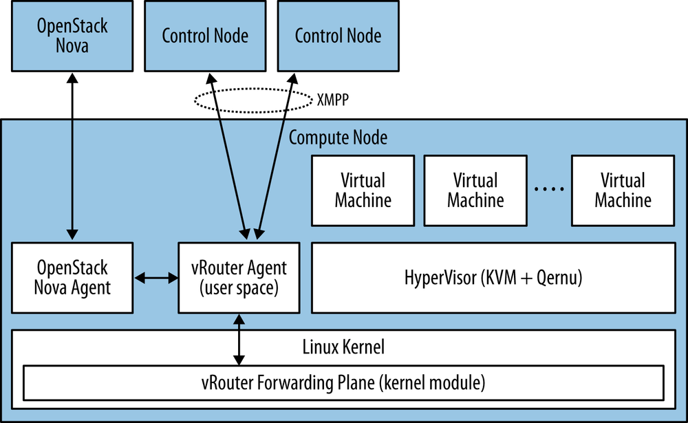
Like all SDN controllers, the Juniper solution requires a paired agent in the network elements, regardless of whether they are real devices or virtualized versions operating in a VM. In the latter case, it’s a hypervisor-resident vRouter combined with a user space VM (vRouter Agent).[100] In the case of the former, configuration via Netconf, XMPP, and the standard BGP protocol are used for communication.
The communication/messaging between Control Node and vRouter Agent is intended to be an open standard using XMPP as the bearer channel. The XMPP protocol is a standard, but only defines the transport of a “container” of information. The explicit messaging contained within this container needs to be fully documented to ensure interoperability in the future.
Several RFCs have been submitted for this operational paradigm. These cover how the systems operate for unicast, multicast, and the application of policy/ACLs:
An additional RFC has been submitted for the IF-MAP schema for transfer of non-operational state:
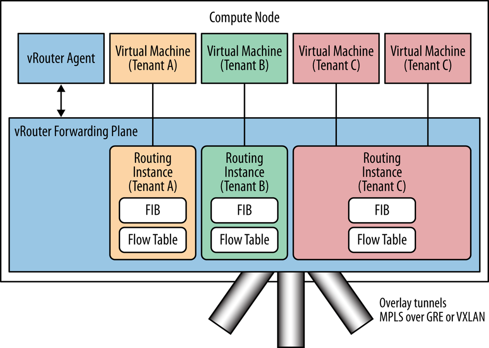
The vRouter Agent converts XMPP control messages into VRF instantiations representing the tenants and programs the appropriate FIB entries for these entities in the hypervisor resident vRouter forwarding plane, illustrated in Figures 4-16 and 4-17.
The implementation uses IP unnumbered interface structures that leverage a loopback to identify the host physical IP address and to conserve IP addresses. This also provides multitenant isolation via MPLS labels supporting MPLS in GRE or MPLS in VxLAN encapsulations. The solution does not require support of MPLS switching in the transit network. Like the VMware/Nicira solution(s), this particular solution provides a software-based gateway to interface with devices that do not support their agent.
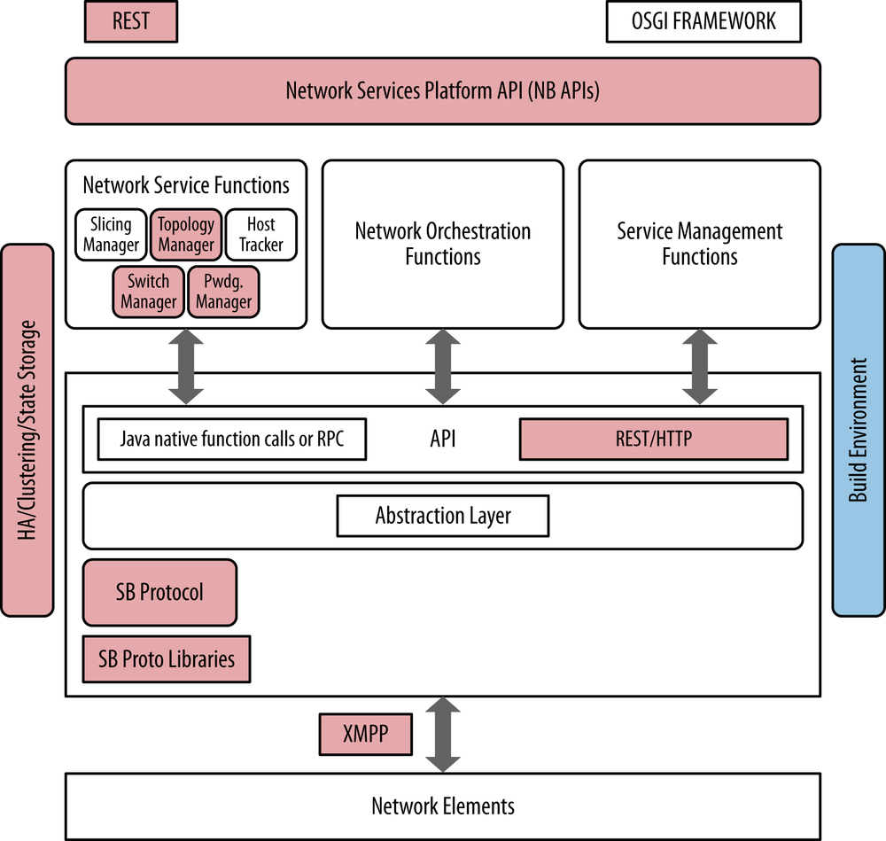
Relationship to the idealized SDN framework
Figure 4-18 maps the relationship of the Juniper Contrail Controller’s components to the idealized SDN framework, with the areas highlighted that the controller implements. In this case, the platform implements a RESTful northbound API that applications and orchestrators can program to, including the OpenStack API integration. There are also integrated HA/clustering and both in-memory and noSQL state storage capabilities. In terms of the southbound protocols, we mentioned that XMPP was used as a carrier channel between the controller and virtual routers, but additional south bound protocols such as BGP are implemented as well.
Path Computation Element Server
RSVP-TE problem statement
In an RSVP-TE network, TE LSPs are signaled based on two criteria: desired bandwidth (and a few other constraints) and the available bandwidth at that instant in time the LSP is signaled within in the network.
The issue then is that when multiple LSPs (possibly originating at different LSRs in the network) signal TE LSPs simultaneously, each is vying for the same resource (i.e., a particular node, link, or fragment of bandwidth therein). When this happens, the LSP setup and hold priorities must be invoked to provide precedence to the LSPs. Otherwise, it would be solely first-come, first-served, making the signaling very nondeterministic. Instead, when an LSP is signaled and others already exist, LSP preemption is used to preempt those existing LSPs in favor of more preferred ones.
Even with this mechanism in place, the sequence in which different ingress routers signal the LSPs determine the actual selected paths under normal and heavy load conditions.
Imagine two sets of LSPs, two with priority 1 (call them A and B) and two with priority 2 (call them C and D). Now imagine that enough bandwidth only exists for one LSP at a particular node. So if A and B are signaled, only one of A or B will be in place, depending on which went first. Now when C and D are signaled, the first one signaled will preempt A or B (whichever remained), but then the last one will remain. If we changed the order of which one signaled first, a different outcome would result.
What has happened is that the combination of LSP priorities and pre-emption are coupled with path selection at each ingress router.
In practice, this result is more or less as desired; however, this behavior makes it difficult to model the true behavior of a network a priori due to this nondeterministic behavior.
Bin-packing
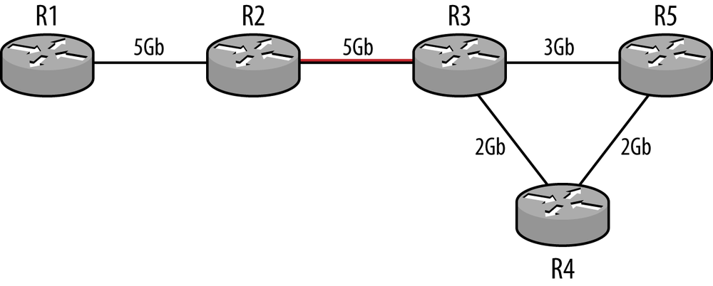
A RSVP LSP gets signaled successfully if there is sufficient bandwidth along its complete path. Many times it is not possible to find such a path in the network, even though overall the network is not running hot.
In Figure 4-19, the numbers in Gb represent the bandwidth available on the links. If one wanted to setup a 4 Gb LSP from R1 to R5, then that setup would fail, because the link R3 to R5 has only 3 Gb available. However the sum of R3-R5 bandwidth and R3-R4-R5 bandwidth is 5Gb (3+2). Thus, there is bandwidth available in the network, but due to the nature of RSVP signaling, one cannot use that available bandwidth.
Thus, the bin-packing problem is “how do we maximally use the available network bandwidth?”
Deadlock
Additionally, deadlock or poor utilization can occur if LSP priorities are not used or if LSPs with the same priority collide. In Figure 4-19, if R1 tried to signal a 3 GB LSP to R5 (via R1-R2-R3-R5) and R2 tried to signal a 2GB LSP to R5 (via R2-R3-R5), then only one will succeed. If R2 succeeded, then R1 will be unable to find a path to R5.
The PCE Solution
Prior to the evolution of PCE, network operators addressed these problems through the use of complex planning tools to figure out the correct set of LSP priorities to get the network behavior they desired and managed the onerous task of coordinating the configuration of those LSPs. The other alternate was to over-provision the network and not worry about these complexities.
Path computation element (PCE) allows a network operator to delegate control of MPLS label switched paths (LSPs) to an external controller.
When combined with BGP-LS’ active topology (discussed in Chapter 8), network operators can leverage those (previously mentioned) complex tools with a greatly simplified configuration step (via PCE) to address these problems (in near real time).
There are multiple components of the PCE environment: a PCE server, a PCE client (PCC), and the PCE Protocol that is the protocol for data exchange between the PCE server and PCC.
PCE has evolved through several phases in which:
The server manages pre-configured LSPs in a stateless manner.
The server manages pre-configured LSPs stateless fashion.
The server manages pre-configured and dynamically created LSPs in a stateful way.
The PCE server provides three fundamental services: path computation, state maintenance, and infrastructure and protocol support. The PCE server uses the PCE Protocol in order to convey this information to network elements or PCCs. Ideally, the PCE server is a consumer of active topology. Active topology is derived at least in part from the BGP-TE/LS protocol, although as well as other sources such as routing protocol updates, the new I2RS general topology, and ALTO servers.
As PCE servers evolve, the algorithm for path computation should be loosely coupled to the provisioning agent through a core API, allowing users to substitute their own algorithms for those provided by vendors. This is an important advance because these replacement algorithms now can be driven by the business practices and requirements of individual customers, as well as be easily driven by third-party tools.
Relationship to the idealized SDN framework
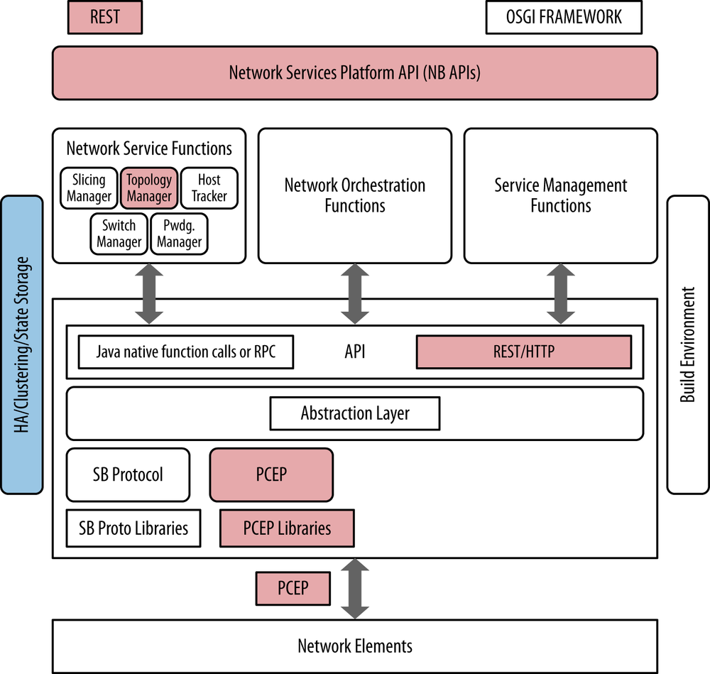
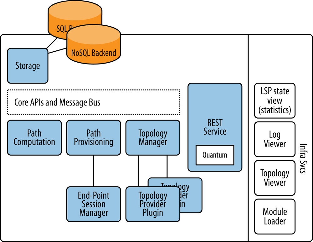
The PCE server or controller takes a noticeably narrow slice of the idealized SDN framework, as shown in Figure 4-20. In doing so, it of course provides a RESTful northbound API offering a myriad of programmability options but generally only interfaces using a single southbound protocol (PCE-P). It is for this reason that we generally view the PCE controller as being an adjunct to existing controllers, which can potentially expand that base functionality greatly.
The other components in this controller solution would be typical of an SDN controller and would include infrastructure for state management, visualization, component management, and a RESTful API for application interface, as shown in Figure 4-21. In terms of the APIs, these should include standard API conversions like an OpenStack Quantum plug-in to facilitate seamless integration with orchestration engines.
The original application of a PCE server was the creation of inter-area MPLS-TE tunnels with explicit paths. The motivation was simply to avoid the operational hurdles around inter-provider operational management, which even today, still remains as a big issue. The PCE server could act as an intermediate point that had sufficient visibility into each provider’s networks to establish paths whose placement was more optimal than those established using routing protocols that only had local visibility within each component provider network. There are also compelling use cases in backbone bandwidth management, such as more optimal bin packing in existing MPLS LSPs, as well as potential use cases in access networks for things such as service management.
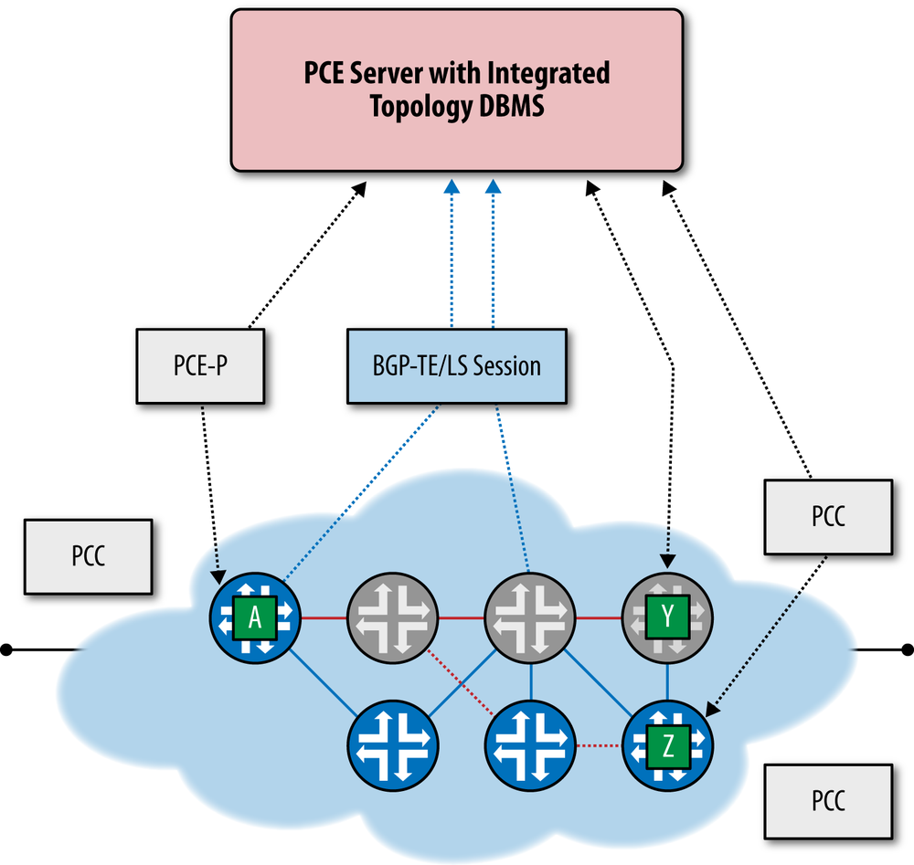
The MPLS Traffic Engineering Database (MPLS TED) was originally distributed as extensions to the IGP database in traditional IP/MPLS networks. Typically, this distribution terminates at area borders, meaning that multiarea tunnels are created with an explicit path only to the border of the area of the tunnel head end. At the border point, a loose hop is specified in the ERO, as exact path information is not available. Often this results in a suboptimal path. As a solution to this problem, BGP-TE/LS allows the export of the TED from an area to a central topology store via a specific BGP address family. The central topology store could merge the area TEDs, allowing an offline application with a more global view of the network topology to compute an explicit end-to-end path.
Because MPLS LSPs provide an overlay using the MPLS encapsulation that is then used to switch traffic based on the MPLS label, the PCE server can either by itself or in conjunction with other SDN technologies function as an SDN controller (see Figure 4-22). These MPLS LSPs are signaled from the “head end” node via RSVP-TE. In this way, this PCE-based solution can signal, establish, and manage LSP tunnels that cross administrative boundaries or just routing areas more optimally or simply differently based on individual constraints that might be unavailable to the operator due to the equipment not implementing it.
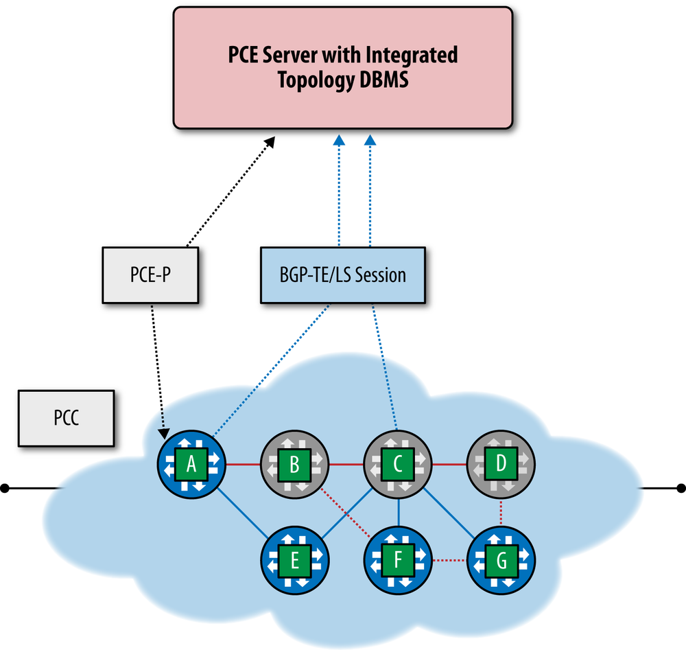
Another emerging use of the PCE server is related to segment routing.[101] In a segment routing scenario, the PCE server can create an LSP with a generalized ERO object that is a label stack. This is achieved through programmatic control of the PCE server. The PCC creates a forwarding entry for the destination that will impose a label stack that can be used to mimic the functionality of an MPLS overlay (i.e., a single label stack) or a traffic engineering (TE) tunnel (i.e., a multilabel stack) without creating any signaling state in the network. Specifically, this can be achieved without the use of either the RSVP-TE or LDP protocols.[102]
Besides the obvious and compelling SDN application of this branch of PCE in network simplification in order to allow a network administrator to manipulate the network as an abstraction with less state being stored inside the core of the network, there is also some potential application of this technology in service chaining.
The association of a local label space with node addresses and adjacencies such as anycast loopback addresses drives the concept of service chaining using segment routing. These label bindings are distributed as an extension to the ISIS protocol:
Node segments represent an ECMP-aware shortest path.
Adjacency segments allow the operator to express any explicit path.
The PCE server can bind an action such as swap or pop to the label. Note that the default operation being “swap” with the same label.
In Figure 4-23, a simple LSP is formed from A to D by imposing label stack 100 that was allocated from the reserved label space. This label stack associates the label with D’s loopback address—(i.e., the segment list is “100”). An explicit (RSVP-TE) path can be dictated through the use of an adjacency label (e.g., 500 to represent the adjacency B-F) in conjunction with the node label for D and B (e.g., 300) creating the segment list and its imposed label stack (i.e., “300 500 100”).
While extremely promising and interesting, this proposal is relatively new, and so several aspects remain to be clarified.[103]
It should be noted that PCE servers are already available from Cisco Systems, which acquired Cariden Technologies. Cariden announced a PCE server in 2012.[104] Other vendors with varying solutions for how to acquire topology, how to do path computation, and other technical aspects of the products are also working on PCE server solutions. In addition to these commercial offerings, a number of service providers, including Google, have indicated that they are likely to develop their own PCE servers independently or in conjunction with vendors in order to implement their own policies and path computation algorithms.
Plexxi
Plexxi Systems are based around the concept of affinity networking, offering a slightly different kind of controller—a tightly coupled proprietary forwarding optimization algorithm and distribution system.
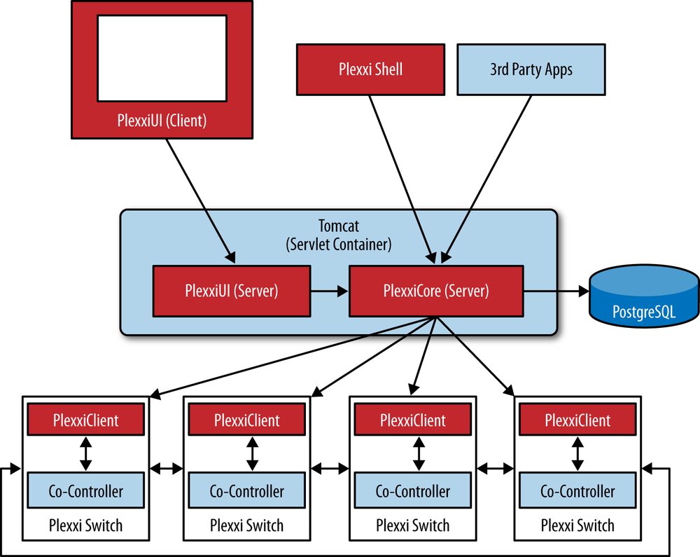
The Plexxi controller’s primary function is to gather information about affinities dynamically from external systems or statically via manually created policies and then translate this affinity information into forwarding topologies within the Plexxi network. See Figure 4-24 for a sketch of the Plexxi Systems architecture.
The Plexxi physical topology is ring based, and affinities are matched to ring identifiers, thus forming a tight bond between the overlay and underlay concepts. Some would say this tight bond is more of a hybrid, or blending into a single network layer.
These topologies manifest as a collection of forwarding rules pushed across the switches within the controller’s domain. There are additional mechanisms in place that preserve active topology on the switches if the controller(s) partition from the network.
The controller tasks are split between a controller and co-controller, where the central controller maintains central policy and performs administrative and the algorithmic fitting tasks, while the co-controller performs local forwarding table maintenance and fast repair.
In addition to learning about and creating affinities, the controller provides interfaces for operational and maintenance tasks. These interfaces include a REST API, a Jython shell, and a GUI. The Jython shell has numerous pre-shipped commands for working with the controller and the switches, however custom CLI commands can easily be created with a bit of Python coding. The GUI employs the JIT/GWT to auto-create interactive diagrams of the physical network and the affinities it supports.
The Plexxi topology and forwarding programming are part of a proprietary control protocol (PSCP). The forwarding programming uses ActiveMQ and the controller is based around PostgreSQL.[105]
The Plexxi control paradigm currently works only with Plexxi’s LightRail optical switches.
Plexxi scale is up to 250 switches per ring per controller pair. Plexxi supports redundant and multiring topologies for scale and the separation of maintenance domains.[106]
The Plexxi relationship to the idealized controller would be the same as others with a proprietary southbound API (much like the Contrail VNS comparison in Figure 4-18), with the notable exception that the affinity algorithms provide differentiation in topology and forwarding.
Plexxi Affinity
An affinity consists of one or two affinity groups and an affinity link between them. An affinity group is a collection of endpoints, identified by MAC or IP address. An affinity link is a policy construct describing a desired forwarding behavior between two affinity groups or the forwarding behavior between endpoints within a single affinity group.
For instance, affinity group A can be a set of MAC addresses belonging to storage cluster members. Affinity group B can be a pair of redundant storage controllers. An affinity link between group A and group B can tell the controller to isolate this traffic in the network. Affinity information can be harvested from any type of infrastructure system through Plexxi connectors: IP PBXs, storage systems, WAN optimization systems, private cloud systems such as OpenStack, VMware deployments, and so on. In addition to these, affinities can be derived from flow-monitoring systems that store sFlow, netflow, or IPFIX data.
Cisco OnePK
The Cisco OnePK controller is a commercial controller that embodies the framework concept by integrating multiple southbound protocol plug-ins, including an unusual southbound protocol plug-in, the Cisco OnePK API.
The architecture is a Java-based OSGI framework that uses an in-memory state storage model and provides a bidirectional (authenticated) REST interface. Clustering is supported using Infinispan and JBoss marshaling and transaction tools. See Figure 4-25 for a sketch of the Cisco OnePK controller concept.
Cisco claims the controller logic is capable of reconciling overlapping forwarding decisions from multiple applications and a service abstraction that allows troubleshooting as well as capability discovery and mapping.
While it’s not unusual for the major network equipment vendors to offer their customers an SDK (a vendor-specific, network element programmability option that pre-dates SDN), the Cisco controller implements this as a plug-in in the generalized framework concept. This opens the door to the continued use of their SDK in an SDN solutions environment (e.g., blending the OnePK API with OpenFlow) in places where the SDK (or SDK apps on the controller) can add value.
Relationship to the Idealized SDN Framework
The Cisco OnePK controller appears to be the best mapping of functionality within a controller to the idealized SDN framework. It contains all aspects of the idealized controller in that it provides an extensible RESTful API, an integrated development environment, multiple computational engines, as well as different southbound protocols through which it can be used to interface to what is likely the widest variety of network devices real and virtual. The controller contains capabilities for both memory resident and offline, and distributed state management and configuration storage. It also contains provisions for horizontal controller-to-controller communication and coordination. Finally, in order to facilitate the Swiss Army knife of northbound and southbound protocols, the controller implements an abstraction layer that facilitates the many-to-many communication channels needed to program such a controller. It is this that really differentiates it from the other controllers discussed in that it can be further extended in the future with relative ease.
Based on these advantages, it is also no surprise that this controller is also used as the new gold standard for open source SDN controllers, as evidenced by it being the basis for the new OpenDaylight Project Linux Foundation consortium.
Conclusions
The term SDN controller can have many different meanings and thus exists in many different forms today. Much of the meaning is derived from the network domain in which the controller will operate, was derived from, and the strategy and protocol choices used in that domain.
The current state of the SDN controller market is that, while there is an expectation of standards-based behaviors whereby users often cite multivendor interoperability for provisioning as a compelling feature of SDN, this is not always the case. This fact remains, for better or worse. Vendors may use proprietary techniques and protocols that depend on the ubiquity of their products or the compelling nature of their applications to create markets for their products. The latter is true because applications were originally (and still are currently) closely bound to the controller in the SDN market through use of non-standardized APIs.
Because of the controller/agent relationship and the reality that not all existing network elements may support the agent daemon/process of the controller (that instantiates the protocol that delivers the network state required to create the aforementioned network abstractions), many controller product strategies also involve the use of host-based gateway solutions. In these gateways, the agents transform the tenant overlay networks into a common digestible format for non-controlled elements—typically turning the tenant overlay networks into VLANs. This strategy allows the interoperation of the old and the new networks with the caveats that the software-based gateway may be of lower packet processing capability—with a potential performance penalty.
The controllers surveyed[107] have the following general attributes when considered as a group:
They provide various levels of development support—languages, tooling, etc.
Commercial offerings tend to have proprietary interfaces but (as expected) offer more robust storage and scale traits today.
The evolution of network-state specific controllers versus integrated data center solution controllers has led to new strategies for state storage in more recently developed products (e.g., the use of NoSQL databases by Big Switch Networks), messaging (e.g., Redis in the Juniper Networks solution), entity management (e.g., the use of Zookeeper). In the end, commercial offerings have to adopt a stance on state sharing (either atomic operation or federation).
All SDN controller solutions today have a very limited view of topology. This is predominantly a single layer of the network or even only locally adjacent devices such as the case when using LLDP for layer 2, or in the case of PCE, the BGP traffic-engineering database.
Few controllers support more than a single protocol driver for interaction with clients/agents. Some OpenFlow open source controllers don’t support NETCONF and thus can’t support of-config, for example.
All controller solutions today have proprietary APIs for application interfaces. That is, no standard northbound interface exists in reality, although some are attempting to work on this problem such as the Open Daylight Project. Unfortunately the ONF has resisted working in this area until very recently, but other standards organizations such as the IETF and ETSI have begun work in this area. Also, the Open DayLight Project will be producing the open source code that will represent a useful and common implementation of such an interface, which may very well drive those standards.
At best, the present SDN controllers address scalability by supporting multicontroller environments or with database synchronization and/or clustering strategies. These strategies hamper interoperability between vendors with the exception of the Juniper solution, which proposes the use of BGP for exchanging network state but still requires adoption by other vendors.
In the OpenFlow environment, the horizontal and vertical scalability of open source SDN controllers is questionable, since robust support of underlying DBMS backends is fairly new. Many were designed originally to run with memory resident data only. That is, they were not designed to share memory resident state between clustered controllers unless they are architected specifically. Big Switch Networks may be an exception, but many of their enhancements were reserved for their commercial offering.
Support for OpenFlow v1.3 is not yet universal. Most controllers and equipment vendors still only support OpenFlow 1.0. This can be an issue because a number of critical updates were made to the protocol by 1.3. Furthermore, along the lines of support for OpenFlow, many device vendors have implemented a number of vendor-proprietary extensions to the protocol that not all controllers support. This further puts a dent into interoperability of these solutions.
Most network-related discussions eventually come to the conclusion that networks are about applications. In the case of the SDN controller, application portability and the ecosystem that can be built around a controller strategy will ultimately decide on who the commercial victor(s) are. If none is sufficient when it comes to controllers, then an evolution in thinking about SDN and the controller paradigm may occur as well. This may be happening in how the Cisco OnePK (and the Open Daylight Project) controller has been created. Flexibility was absent from most controller architectures both in terms of southbound protocol support and northbound application programmability.
There are some notable technologies or thought processes in the surveyed SDN controllers regarding application development:
The Trema model introduces the idea of a framework, in that it originally provided just a development core and each service module provided its own API that can then be implemented by more components or end-user applications.
Big Switch Network’s commercial product and potentially Floodlight, as well as the Spring-based environment for VMware accentuate API development tooling, in particular the ability to autogenerate APIs from modules or generate them from data models that the modules manipulate.
Juniper Networks refines the idea with the idea of compilation by invoking the SDN as network compiler concept. This created high-level, user-friendly/app-friendly, data models that translate into lower-level network strategy/protocol specific primitives (e.g., L3VPN VRFs, routes, and policies).
Several vendors have strategies that acknowledge the need for separate servers for basic functionality (even more so for long-term scalability) and potentially application-specific database strategies. As we get to more recent offerings, many are described as systems or clusters, which must define and address a consistency philosophy.
We’ve seen that, as we survey across time, the best of ideas like these are culled or evolve, and are then incorporated in new designs.
[60] Some vendors provide both open source and commercial products.
[63] vCenter Server can run on bare metal or in a VM. When run in a VM, vCenter can take advantage of vSphere high-availability features.
[65] The environment is provided through a subsidiary: SpringSource.
[68] Licensing has had per socket and VRAM entitlement fees, with additional fees for applications like Site Recovery Manager. While this may be a “hearsay” observation, we have interviewed a large number of customers.
[70] ESX, ESXi, Xen, Xen Server, KVM, and HyperV.
[72] http://blogs.vmware.com/console/2012/07/vmware-and-nicira-advancing-the-software-defined-datacenter.html
[76] Both NOX and POX information can be accessed via http://www.noxrepo.org/forum/.
[79] A new fork of NOX that is C++ only was created.
[83] There was some discussion of an SQLite interface for Trema.
[84] The entire environment can be run on a laptop, including the emulated network/switches.
[88] While our focus is on the very familiar open source Floodlight, for the sake of comparison, the commercial BNC is also weighed. With BNC, BigSwitch offers virtualization applications and its BigTap application(s).
[89] This is not an exhaustive list of BNS commercial applications (but critical ones to compare it to the idealized controller).
[90] In their commercial offering, Big Switch Networks combines the support of a NoSQL distributed database, publish/subscribe support for state change notification, and other tooling to provide horizontal scaling and high availability. This is a fundamental difference between commercial and open source offerings (in general).
[95] http://www.nuagenetworks.net/press-releases/nuage-networks-introduces-2nd-generation-sdn-solution-for-datacenter-networks-accelerating-the-move-to-business-cloud-services/
[97] Juniper doesn’t insist on Cassandra as the NoSQL database in their architecture and publishes an API that allows substitution.
[100] Similar to the Nicira/VMware ESX situation prior to merge in recently announced NSX product.
[102] Arguably, the reduction of complexity in distributed control plane paradigms (at least session-oriented label distribution) is an SDN application.
[103] http://datatracker.ietf.org/doc/draft-gredler-rtgwg-igp-label-advertisement/
http://datatracker.ietf.org/doc/draft-gredler-isis-label-advertisement/
[104] http://www.sdncentral.com/sdn-blog/cardien-technologies-releases-service-provider-infrastructure-sdn-white-paper/2012/08/
[105] Database replication will enable (on Plexxi roadmap for 2013) configuration and state replication in multicontroller or redundant environments.
[106] Plexxi offers comprehensive network design guidance and has a roadmap for larger scale and more complex topologies.
[107] This is not an exhaustive list and doesn’t include all currently available or historic SDN controller offerings.
Get SDN: Software Defined Networks now with the O’Reilly learning platform.
O’Reilly members experience books, live events, courses curated by job role, and more from O’Reilly and nearly 200 top publishers.
