In the previous chapters, we covered reverse engineering on traditional platforms such as Win32 and Linux. However, what about the little guys? Can you reverse engineer software on embedded operating systems? Why would you want to?
Many embedded operating systems are stripped-down microversions of their big brothers. An embedded operating system brings the power of a complete OS to small devices such as mobile phones or watches, which suffer from severely restricted processing and memory resources. However, as embedded devices continue to increase in sophistication, their vulnerability to attack increases as well. Already the first computer viruses have hit embedded platforms, as we describe in Chapter 17. Corporate spyware will likely follow soon. With hundreds of millions of “smart” consumer appliances on the horizon, the potential for abuse keeps increasing.
Embedded RCE is still in its infancy. In this chapter, we introduce embedded OS architecture and how to crack the applications that run on it. For our example, we have chosen Windows CE, which powers many Windows Mobile OS flavors such as PocketPC and Smartphone. Windows CE is a semi-open, scalable, 32-bit, true-multitasking operating system that has been designed to run with maximum power on minimum resources. This OS is actually a miniature version of Windows 2000/XP that can run on appliances as small as a watch.
Why have we chosen Windows CE for our reverse engineering research, instead of friendly, open source, and free embedded Linux? For better or worse, CE is set to become one of the most prevalent operating systems of all time, thanks to aggressive marketing tactics by Microsoft. In addition, because of their closed nature, Windows platforms usually see the majority of viruses and unethical corporate spyware. Thus, the need to reverse engineer embedded Windows applications is more pressing. Download the free eMbedded Visual Tools (MVT) package from Microsoft.com and get cracking—literally.
Windows CE is the basis of all Windows Mobile PocketPC and Smartphone devices. In addition, using the CE Platform Builder, any programmer can create her own miniature operating system based on Windows CE. Consequently, CE is starting to control a vast array of consumer devices, ranging from toasters to exercise bicycles. Because of its growing prevalence, if you want to become proficient at reverse engineering applications on mobile devices it is important to understand the basics of how this operating system works. This segment briefly covers the Windows CE architecture, with a deeper look at topics important to understand when reversing.
In the world of miniature gadgets, physics is often the rate-limiting step. For example, the intense heat generated by high-speed processors in notebook PCs has been shown to be hot enough to fry eggs. In fact, News.com reported that one unfortunate man inadvertently burned his genitals with a laptop computer (http://www.news.com.au/common/story_page/0,4057,5537960%255E1702,00.html)!
Windows CE devices are likewise limited in their choice of processors. The following is a list of processors supported by Windows CE:
- ARM
Supported processors include ARM720T, ARM920T, ARM1020T, StrongARM, and XScale. ARM-based processors are by far the most common choice of CE devices at the time of this writing.
- MIPS
Supported processors include MIPS II/32 w/FP, MIPS II/32 w/o FP, MIPS16, MIPS IV/64 w/FP, and MIPS IV/64 w/o FP.
- SHx
Supported processors include SH-3, SH-3 DSP, and SH-4.
- x86
Supported processors include 486, 586, Geode, and Pentium I/II/III/IV.
If heat dissipation is a serious issue, the best choice is one of the non-x86 processors that uses a reduced level of power. The reduction in power consumption reduces the amount of heat created during processor operation, but it also limits the processor speed.
The kernel is the key component of a Windows CE OS. It handles all the core functions of the OS, such as processes, threads, and memory management. It also handles scheduling and interrupts. However, it is important to understand that Windows CE uses parts from its big brother—i.e., desktop Windows software. This means its threading, processing, and virtual memory models are similar to those of traditional Windows platforms.
While CE has a lot in common with traditional Windows, there are several items that distinguish it. These differences center on the use of memory and the simple fact that there is no hard drive (as discussed in the next section). In addition, dynamic link libraries (DLLs) in Windows CE are not implemented as they are in other Windows operating systems. Instead, they are used in such a way as to maximize the available memory. Integrating them into the core operating system means that DLLs don’t take up precious space when they are executed. This is an important concept to understand before trying to reverse a program in Windows CE. Due to this small difference, attempting to break a program while it is executing a system DLL is not allowed by Microsoft’s MVT.
A process in Windows CE represents an executing program. The number of processes is limited to 32, but each process can execute a theoretically unlimited number of threads. Each thread has a 64K memory block assigned to it, in addition to an ID and a set of registers. It is important to understand this concept because when debugging a program, you will be monitoring the execution of a particular thread, its registers, and the allotted memory space. In the process, you will be able to deduce hidden passwords, serial numbers, and more.
Processes can run in two modes: kernel and user. A kernel process has direct access to the OS and the hardware. This gives it more power, but a crash in a kernel process often crashes the whole OS. A user process, on the other hand, operates outside the kernel memory—but a crash only kills the running program, not the whole OS. In Windows CE, any third-party program will operate in user mode, which means it is protected. In other words, if you crash a program while reversing it, the whole OS will not crash (though you still may need to reboot the device).
There are two other important points to understand. First, one process cannot affect the data of another process. While related threads can interact with each other, a process is restricted to its own memory slot. The second point to remember is that each existing thread is continuously being stopped and restarted by a scheduler (discussed next). This is how multitasking is actually performed. While it may appear that more than one program is running at a time, the truth is that only one thread may execute at any one time on single-processor devices.
The scheduler is responsible for managing the thread process times. It does this by giving each thread a chance to use the processor. By continuously moving from thread to thread, the scheduler ensures that each gets a turn. Three key features for adjusting processor time are built into the scheduler.
The first feature is a method that is used to increase the amount of processor time. The secret is found in multithreading an application. Since the scheduler assigns processor time at the thread level, a process with 10 threads will get 10 times the processor time of a process with one thread.
Another method for gaining more processor time is to increase the process priority; but it’s not encouraged unless necessary. Changing priority levels can cause serious problems in other programs, and it affects the speed of the computing device as a whole. The THREAD_PRIORITY_TIME_CRITICAL priority is important; it forces the processor to complete the critical thread.
The final interesting feature of the scheduler deals with a problem that can arise when priority threading is used. If a low-priority thread is executing and it ties up a resource needed by a higher-priority thread, the system could become unstable. In short, a paradox is created in which the high thread waits for the low thread to finish, which in turn waits on the high to complete. To prevent this situation from occurring, the scheduler will detect such a paradox and boost the lower-priority thread to a higher level, thus allowing it to finish.
Note that all of these problems are issues that every Windows OS must deal with. A Windows Mobile device may seem different, but it is still a Microsoft product, and as such it is limited by those products’ common constraints.
One of the unique properties of most devices running Windows CE is the lack of a disc hard drive. Instead of spinning discs, pocket PCs use old-fashioned RAM (Random Access Memory) and ROM (Read Only Memory) to store data. While this may seem like a step back in technology, the use of static memory like ROM is on the rise and will eventually make moving storage devices obsolete. The next few paragraphs explain how memory in a Windows CE device is used to facilitate program execution.
In a Windows CE device, the entire operating system is stored in ROM. This type of memory is typically read-only and is not used to store temporary data that can be deleted. On the other hand, data in RAM is constantly being updated and changed. This memory is used to hold all files and programs that are loaded into the Windows CE-based device.
RAM is also used to execute programs. When a third-party game is executed, it is first copied into RAM and is executed from there. This is why a surplus of RAM is important in a Windows CE device. However, the real importance of RAM is that its data can be written to and accessed by an address. This is necessary because a program will often have to move data around. Since each program is allotted a section of RAM to run in when it is executed, it must be able to write directly to its predefined area.
While ROM is typically only used as a static storage area, in Windows CE it can be used to execute programs. This process is known as Execute In Place (XIP). In other words, RAM is not required to hold the ROM’s data as a program executes. This freedom allows RAM to be used for other important applications. However, it only works with ROM data that is not compressed. While compression allows more data to be stored in ROM, the decompression will force any execution to be done via RAM.
RAM usage on a Windows CE device is divided between two functions. The first is the object store , which is used to hold files and data that are used by the programs but are not stored in ROM. In particular, the object store holds compressed program files, user files, database files, and the infamous Windows registry file. Although this data is stored in RAM, it remains intact when the device is turned off, because the RAM is kept charged by the power supply. This is the reason it is very important to never let the charge on a Pocket PC device completely die. If this happens, the RAM loses power and resets. It dumps all installed programs and wipes everything on the device except what is stored in ROM. This is referred to as a hard reboot when dealing with a Pocket PC device.
The second function of the RAM is to facilitate program execution. As previously mentioned, when a program is running, it needs to store the information it is using—this is the same function that RAM serves on a typical desktop PC. Any data passing through a program, such as a password or serial number, will be written to the RAM at one time or another.
Windows CE does have a limit on the RAM size. In Windows CE 3.0 it is 256 MB with a 32 MB limit on each file, but in Windows CE .NET this value has been increased to a rather large 4 GB. In addition, there is a limit to the number of files that can be stored in RAM (4 million) and to the number of programs that can operate at the same time. This brings us to multitasking.
Windows CE was designed to be a true multitasking operating system. Just like other modern Windows operating systems, it allows more than one program to be open at a time. In other words, you can listen to an MP3 while taking notes and checking out sites on the Internet. Without multitasking, you would be forced to close one program before opening another. However, you must be careful not to open too many programs on a Windows CE device. Since you are limited by the amount RAM in the device, and each open program takes up a chunk of the RAM, you can quickly run out of memory.
Finally, the limitation of RAM in a pocket PC also affects the choice of operating system. Since Windows CE devices may only have 32-128 MB of internal RAM, they do not make good platforms for operating systems that use a lot of memory, such as embedded Windows XP. In this OS, the minimum footprint for a program is 5 MB. On the other hand, Windows CE only requires 200K; this is a 2500% difference.
This part of the Windows CE architecture is responsible for handling all the input (e.g., stylus) and output (e.g., screen text and images). Since every program uses windows to receive messages, it is a very important part of Windows CE. It is one of the areas you need to understand to successfully reverse a program.
Without going into too much detail, you should know that every Windows CE process is assigned its own windows messaging queue. The queue is similar to a stack of papers that is added to and read from. This queue is created when the program calls GetMessage, which is very common in Windows CE programs. While the program executes and interacts with the user, messages are placed in and removed from the queue. The following is a list and explanation of the common commands that you will see while reverse engineering:
- PostMessage
Places message on queue of target thread, which is returned immediately to the process/thread
- SendMessage
Places message on queue, but does not return until it is processed
- SendThreadMessage
Sends messages directly to thread instead of to queue
These Message commands, and others, act as bright, virtual flares when reversing a program. For example, if a “Sorry, wrong serial number” warning is flashed on the screen, you can bet some Message command was used. By looking for the use of this command in a disassembler, you can find the part of the program that needs further research.
We’ve given you a quick inside look at how Windows CE operates. This information is required reading for the rest of the chapter. Understanding processing, memory architecture, and how Windows CE uses messages to communicate with the executing program will make it easier for you to understand how CE cracking works. Just as a doctor must understand the entire human body before diagnosing even a headache, a reverse engineer must thoroughly understand the platform he is dissecting to be successful in making a patch or deciphering a serial number.
To review: when a developer writes a program, he typically uses one of several languages. These include Visual Basic, C++, Java, or any one of the other, lesser-used languages. The choice of language depends on several factors; the most common are space and speed considerations. In the infamously bloated Windows environment, Visual Basic is arguably the king. This is because the hardware required to run Windows is usually more than enough to run any Visual Basic application. However, if a programmer needs a higher level of speed and power, he will probably select C++.
While these upper-level languages make programming easier by providing a large selection of Application Program Interfaces (APIs) and commands that are easy to understand, there are many occasions in which a programmer must create a program that can fit in a small amount of memory and operate quickly. To meet this goal, she may choose to use assembler, thus controlling the hardware of the computer directly. However, programming in assembler is tedious and must be done within an explicit set of rules.
Since every processor type uses its own set of assembler instructions, focus on one device (i.e., one processor type) and become fluent in the operation codes (opcodes), instruction sets, processor design, and methods by which the processor uses internal memory to read and write to RAM. Only after you master the basics of the processor operation can you start to reverse engineer a program. Fortunately, most processors operate similarly, with slight variations in syntax and use of internal processor memory.
Since our target in this chapter is the ARM processor used by PDAs, we provide some of the basic information you need to know, or at least to be familiar with, before attempting to study a program meant to run on this type of processor. The rest of this section describes the ARM processor, its major opcodes and their hex equivalents, and how its memory is used. If you do not understand this information, you may have some difficulty with the rest of this chapter.
The Advanced RISC Microprocessor (ARM) is a low-power, 32-bit microprocessor based on the Reduced Instruction Set Computer (RISC) principles. ARM is generally used in small devices that have a limited power source and a low threshold for heat, such as PDAs, telecommunication devices, and other miniature devices that require a relatively high level of computing power.
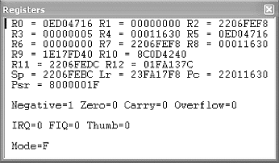
There are a total of 37 registers within this processor that hold values used in the execution of code. Six of these registers are used to store status values needed to hold the results of comparison and mathematical operations, among others. This leaves 31 registers to the use of the program, of which a maximum of 16 are generally available to the programmer. Of these 16, register 15 (R15) is used to hold the Program Counter (PC), which is used by the processor to keep track of where in the program it is currently executing. R14 is also used by the processor, as a subroutine link register (Lr), which is used to temporarily hold the value of R15 when a Branch and Link (BL) instruction is executed. Finally, R13, known as the Stack Pointer (Sp), is used by the processor to hold the memory address of the stack, which contains all the values about to be used by the processor in its execution.
In addition to these first 16 registers, some debuggers allow the programmer to monitor the last 4 registers (28-31), which are used to hold the results of arithmetic and logical operations performed by the processor (e.g., addition, subtraction, comparisons). Here’s a list of the registers and their purposes. They are listed in descending order because the processor bits are read from high to low.
- R31
Negative/less than
- R30
Zero
- R29
Carry/borrow/extend
- R28
Overflow
Understanding these registers is very important when debugging software. If you know what each of these values means, you should be able to determine the next step the program will make. In addition, using a good debugger, you can often alter these values on the fly, thus maintaining 100% control over how a program flows. Table 4-1 shows some possible conditional values and their meanings. It highlights the most common values that you will see in a debugger.
Table 4-1. Sample ARM conditional register values
Negative | Zero | Carry | Overflow | Meaning |
|---|---|---|---|---|
0 | 0 | 0 | 0 | EQ—Z set (equal) |
0 | 0 | 0 | 1 | NE—Zero clear (not equal) |
0 | 0 | 1 | 0 | CS—Carry set (unsigned higher or same) |
0 | 0 | 1 | 1 | CC—Carry clear (unsigned lower) |
0 | 1 | 0 | 0 | MI—Negative set |
0 | 1 | 0 | 1 | PL—Negative clear |
0 | 1 | 1 | 0 | VS—Overflow set |
0 | 1 | 1 | 1 | VC—Overflow clear |
1 | 0 | 0 | 0 | HI—Carry set and Zero clear (unsigned hi) |
1 | 0 | 0 | 1 | LS—Carry clear and Zero set (unsigned lo or same) |
1 | 0 | 1 | 0 | GE—Negative set and Overflow set or Negative clear and Overflow clear (>=) |
1 | 0 | 1 | 1 | LT—Negative set and Overflow clear or Negative clear and Overflow set (<) |
1 | 1 | 0 | 0 | GT—Zero clear, and either Negative set and Overflow set or Negative clear and Overflow clear (>) |
1 | 1 | 0 | 1 | LE—Zero set, and either Negative set and Overflow clear or Negative clear and Overflow set (<=) |
1 | 1 | 1 | 0 | AL—Always |
1 | 1 | 1 | 1 | NV—Never |
Figure 4-1 illustrates Microsoft’s eMbedded Visual Tools (MVT) debugger, showing the values held in registers 0-12, Sp, Lr, and PC. In addition, this figure shows us the four registers (R31-R28) used to hold the conditional values. See if you can determine what condition the program is currently in, using Table 4-1.
The ARM processor has a predefined set of operation codes (opcodes) that allows a programmer to write code. These same opcodes are used by compilers, such as Microsoft’s MVT, when a program is created for an ARM device. They are also used when a program is disassembled and/or debugged. For this reason, you must understand how opcodes are used, as well as what operations they perform. In addition, it is important to have a reference for the hex equivalent of each opcode, in order to find and replace an opcode as it appears in a hex dump of the file. While practice will ingrain the popular opcodes in your memory, this list will get you started.
The Branch opcode tells the processor to jump to another part of the program or, more specifically, the memory, where it will continue its execution. The B opcode is not to be confused with the Branch with Link (BL) opcode, discussed next. The main difference is that the B opcode is simply a code execution redirector. The program jumps to the specified address and continues processing the instructions. The BL opcode also redirects to another piece of code, but it eventually jumps back to the original code and continues executing where it left off.
There are several variations of the B opcode, most of which make obvious sense. The following is a list of the three most common variants and what they mean. Note that this list relates to the condition table in the previous section. In addition, we have included the hex code that you will need to search for when altering a Branch operation. For where to find a full list, please visit the Section 4.5 at the end of the chapter.
B      Branch           Always branches        XX XX XX EA
BEQ    B if equal       B if Z flag = 0        XX XX XX 0A
BNE    B if no equal    B if Z flag = 1        XX XX XX 1A
Here are some examples:
B      loc_11498        07 00 00 EA
BEQ    loc_1147C        0C 00 00 0A
BNE    loc_11474        06 00 00 1A
When a program is executing, there are situations in which the program must branch out and process a related piece of information before it can continue with the main program. This is made possible with a Branch with Link opcode. Unlike its relative, the B opcode, BL always returns to the code it was originally executing. To facilitate this, register 14 is used to hold the original address from which the BL was called.
The BL opcode has several variants to its base instruction, just like the B opcode. The following is a list of the same three variants and what they mean, which will be followed by examples. It is important to note that the examples show function calls instead of address locations. However, if you look at the actual code, you will find normal addresses, just like with the B opcode. The function naming convention is based on the fact that many BL calls are made to defined functions that return a value or perform a service. As you investigate CE reversing, you will become very intimate with the BL opcode. Note that the MVT debugger will not jump to the BL address when doing a line-by-line execution. It instead performs the function and continues to the next line. If you want to watch the code specified by the BL operation, specify a breakpoint at the memory address to which it branches. This concept is discussed later in this chapter.
BL       Branch with Link     Always branches          XX XX XX EB
BLEQ     BL if equal        BL if Z flag = 0         XX XX XX 0B
BLNE     BL if not equal      BL if Z flag = 1         XX XX XX 1B
Here are some examples:
BL        AYGSHELL_34         7E 00 00 EB
BLEQ      mfcce300_699        5E 3E 00 0B
A program is constantly moving data around. In order to facilitate this function, registers are updated with values from other registers and with hardcoded integers. These values are used by other operations to make decisions or perform calculations. This is the purpose of the Move opcode.
MOV does just what its name implies. In addition to basic moves, this opcode has the same conditional variants as the B and BL opcodes. By this point, you have a general understanding of what the EQ/NE/etc. means to an instruction set, so we will not discuss it further. Note, however, that almost every opcode includes some form of a conditional variant.
It’s important to understand how the MOV instruction works. This command can move the value of one register into another, or it can move a hardcoded value into a register. However, notice the item receiving the data is always a register. The following are several examples of the MOV command, what they do, and their hex equivalents.
MOV    R2, #1    01 20 A0 E3      Moves the value 1 into R2
MOV    R3, R1    01 30 A0 E1      Moves value in R1 into R3
MOV    LR, PC    0F E0 A0 E1      Moves value of R15 into R14[1]
MOV    R1, R1    01 10 A0 E1      Moves value R1 into R1[2]
Programs constantly need to compare two pieces of information. The results of the comparison are used in many ways: from the validation of a serial number, to continuation of a counting loop, etc. The assembler instruction set that is responsible for this process is Compare, or CMP.
The CMP operation can be used to compare the values in two registers with each other or to compare a register value and a hardcoded value. The results of the comparison do not output any data, but they do change the status of the conditional Zero flag. If the two values are equal, the Zero flag is set to 0; if the values are not equal, the flag is set to 1. This Zero value is then used by a subsequent opcode to control what is executed, or how.
The CMP operation is used in almost every serial number validation. The validation is accomplished in two ways: first, the actual comparison of the entered serial number with a hardcoded serial number; and second, after the validation check, when the program is deciding what piece of code is to be executed next. Typically, there will be a BEQ (Branch if Equal) or BNE (Branch if Not Equal) operation that uses the status of the Zero flag to either send a “Wrong Serial Number” message to the screen or accept the entered serial and allow access to the protected program. This use of the CMP operation is discussed further later in this chapter.
Another use of CMP is in a loop function. Loop functions assist in counting, string comparisons, file loads, and more. Being able to recognize a loop in a sequence of assembler programming is an important part of successful reverse engineering. The following is an example of how a loop looks when debugging a program.
00002AEC             ADD       R1, R4, R7
00002AF0             MOV       R0, R6
00002AF4             BL        sub_002EAC
00002AF8             ADD       R5, R5, #20
00002AFC             ADD       R2, R5, #25
00002A00             CMP       R3, R2
00002A04             BEQ       loc_002AEC
This is a simple loop included in an encryption scheme. In memory address 2A04, you can see a Branch occurs if the Zero flag is set. This flag is set, or unset, by memory address 2A00, which compares the values between R3 and R2. If they match, the code jumps back to memory address 2AEC.
The following are examples of two CMP opcodes and their corresponding hex values.
CMP     R2, R3    03 00 52 E1
CMP     R4, #1    01 00 54 E3
While the registers are able to store small amounts of information, the processor must access the space allotted to it in the RAM in order to store larger chunks of information. This information includes screen titles, serial numbers, colors, settings, and more. In fact, almost everything that you see when you use a program has at one time resided in memory. The LDR and STR opcodes are used to write and read this information to and from memory.
While related, these two commands perform opposite actions. The Load (LDR) instruction loads data from memory into a register, and the Store (STR) instruction stores the data from the registry into memory for later usage. However, there is more to these instructions than the simple transfer of data. In addition to defining where the data is moved, the LDR/STR commands have variations that tell the processor how much data is to be moved. The following is a list of these variants and what they mean:
- LDR/STR
Move a word (four bytes) of data to or from memory.
- LDRB/STRB
Move a byte of data to or from memory.
- LDRH/STRH
Move two bytes of data to or from memory.
LDR/STR commands are different from the other previously discussed instructions in that they almost always include three pieces of information, due to the way the load and store instructions work. Since only a few bytes of data are moved, at most, the program must keep track of where it was last writing to or reading from. It must then append to or read from where it left off at the last read/write. You’ll often find LDR/STR commands in a loop where they read in or write out large amounts of data, one byte at a time.
The LDR/STR instructions are also different from other instructions in that they typically have three variables controlling where and what data is manipulated. The first variable is the data that is actually being transferred. The second and third variables determine where the data is written, and if it is manipulated before it is permanently stored or loaded. The following lists examples of how these instruction sets are used.
STR    R1, [R4, R6]           Store R1 in R4+R6
STR    R1, [R4, R6]!          Store R1 in R4+R6 and write the address in R4
STR    R1, [R4], R6           Store R1 at R4 and write back R4+R6 to R4
STR    R1, [R4, R6, LSL#2]    Store R1 in R4+R6*2 (LSL discussed next)
LDR    R1, [R2, #12]          Load R1 with value at R2+12.
LDR    R1, [R2, R4, R6]       Load R1 with R2+R4+R6
Notice the two new items that affect how the opcodes perform. The first is the “!” character, used to tell the instruction to write the new information back into one of the registers. The second is the use of the LSL command, which is discussed next.
Also related to these instructions are the LDM/STM instructions. These are also used to store or load register values; however, they do it on a larger scale. Instead of just moving one value, like LDR/STR, the LDM/STM instructions store or load all the register values. They are most commonly used when a BL occurs. When this happens, the program must be able to keep track of the original register values, which will be overwritten with values used by the BL code. So, they are stored into memory; then, when the branch code is completely executed, the original register values are loaded back into the registers from memory.
The above information should be easy to absorb for those of you who have previous experience with assembler or who are innately good programmers. However, if you are a newcomer, do not be discouraged, as mastering assembler typically takes years of dedicated study.
The final instruction sets we examine are the shifting operations. These are somewhat complicated, but they are a fundamental part of understanding assembler. They are used to manipulate data held by a register at the binary level. In short, they shift the bit values left or right (depending on the opcode), which changes the value held by the register. The following tables illustrate how this works with the two most common shifting instruction sets, Logical Shift Left, or LSL (Table 4-2), and Logical Shift Right, or LSR (Table 4-3). Because of space limitations, we will only be performing shifts on bits 0-7 of a 32-bit value. The missing bit values will be represented by ellipses (...).
Table 4-2. Logical Shift Left (LSL) shifts the 32-bit values left by x number of places, using zeros to fill in the empty spots
LSL | Original decimal | Original binary | New binary | New decimal |
|---|---|---|---|---|
2 | 2 | ...00000010 | ...00001000 | 8 |
3 | 6 | ...00000110 | ...00110000 | 48 |
Table 4-3. Logical Shift Right (LSR) shifts the 32-bit values right by x number of places, using zeros to fill in the empty spots
LSR | Original decimal | Original binary | New binary | New decimal |
|---|---|---|---|---|
4 | 30 | ...00011110 | ...00000001 | 1 |
3 | 25 | ...00011001 | ...00000011 | 3 |
While these are the most common shift instructions, there are three others that you may see. They are Arithmetic Shift Left (ASL), Arithmetic Shift Right (ASR), and Rotate Right Extended (ROR). All of these shift operations perform the same basic function as LSL/LSR, with some variations. For example, the ASL/ASR shifts fill in the empty bit places with the bit value of register 31, which preserves the sign bit of the value being held in the register. The ROR shift, on the other hand, carries the bit value around from bit 0 to bit 31.
The previous pages have given you a brief look at assembler programming on ARM processors. You will need this information later in this chapter when we practice some of our RCE skills on a test program—it will be valuable as you attempt to debug software, find exploits, and dissect hostile code.
For this section, you will need to use the tools described in previous chapters, including hex editors and disassemblers. We start by creating a simple “Hello World!” application, and we then use this program to demonstrate several cracking methods. After this discussion, we offer a hands-on tutorial that allows you to walk through real-life examples of how reverse engineering can be used to get to the heart of a program.
When learning a programming language, the first thing most people do is to create the famous “Hello, World” application. This program is simple, but it helps to get a new programmer familiar with the syntax structure, compiling steps, and general layout of the tool used to create the program. In fact, Microsoft’s eMbedded Visual C++ goes so far as to provide its users with a wizard that creates a basic “Hello World” application with the click of a few buttons. The following are the required steps:
Open Microsoft eMbedded Visual C++.
Click File → New.
Select the Projects tab.
In the “Project Name:” field, type “test”, as illustrated in Figure 4-2. Select WCE Application on the left.
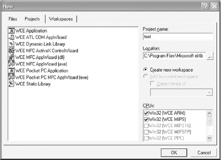
Tip
By default, all compiled executables will be created in the C:\Program Files\Microsoft eMbedded Tools\Common\EVC\MyProjects\ directory.
Click OK.
Ensure “A typical `Hello World!’ Application” is selected, and click Finish.
Click OK.
Tip
We’re running the programs on a PDA synchronized with our computer, but the beauty of Microsoft’s eMbedded Visual Tools is you don’t need a real device. The free MVT has an emulator for virtual testing .
After a few seconds, a new “test” class appears on the left side of the screen, under which are all the classes and functions automatically created by the wizard. We aren’t making any changes to the code, so next, we compile and build the executable:
Ensure the device is connected via ActiveSync.
Click Build → test.exe.
Click Yes/OK through the warnings.
Locate the newly created executable in your C:\Program Files\Microsoft eMbedded Tools\Common\EVC\MyProjects\ directory, or whatever directory you selected during the wizard, and copy it to your device.
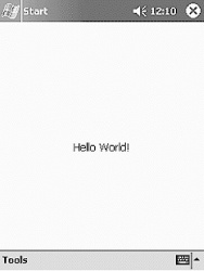
Once the steps are complete, find test.exe on your device and execute it. If everything went according to plan, you’ll see a screen similar to Figure 4-3. After a short break to discuss some of the popular methods crackers use to subvert protection, we will take a closer look at test.exe and make some changes to it using our reversing tools.
In this section, we briefly review some of the cracking techniques discussed in earlier chapters and apply them to embedded reverse engineering. Users who feel comfortable with the Windows CE OS can skip to Section 4.3.3.
In about 80% of all software, there is a common flaw that leads to the eventual cracking of the software: predictable code. For example, if you go through the registration process, you will almost always find a message that tells you the wrong serial number was entered. While this is a nice gesture for the honest person who made a mistake, it is a telltale sign that the program is an easy crack.
The problem arises simply because there are a limited number of alert boxes that appear in a program. A cracker has only to open the program in IDA Pro and search the strings for any calls made to MessageBoxW—the name of the function responsible for sending a message to the computer screen.
Once the cracker finds this call, she can use the reference list included with IDA Pro to backtrack through the program until she finds the point where the serial number is verified. In other words, using a message box to warn about an invalid serial gives the cracker the necessary starting point to look for a weakness. Without it, a beginner cracker could spend hours slowly stepping through the program, testing and probing.
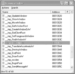
Other common calls are Load String (for loading serial number values into a variable), Registry checks (for checking to see if the program is registered or not), and System Time checks (for checking for trial period deadlines). To find these, a cracker only has to use the Names window, which lists all the functions and system calls used in the program. Figure 4-4 is taken from IDA Pro, with our test.exe program loaded into it. The highlighted function may be a good place to start when looking for a way to alter the displayed message.
When working with strings such as usernames, serials, or other text entries, it is important to monitor the length. The length of the string is important for two reasons. One, a program that expects a string may generate an error if it receives a variable with no value. For example, if a program is trying to divide two numbers and the denominator is blank, the calculation will fail. To avoid problems like this, a program will include checks to ensure that a value is indeed entered.
The second main use of string length checks is when setting aside memory for a variable. For example, our “Hello, World!” application must set aside enough memory for a 12-character variable. The program checks to see how much space is required using wcslen, as the following code illustrates:
ADD  R0, SP, #0x54;    Points R0 to memory address of 'Hello World!' string.
BL    wcslen;    Tests the length of the string and places that value in R0.
While testing string length is undeniably important, it is also an easy function to find and abuse. Because these types of functions are required when verifying serial numbers, a cracker has only to look in the Names window of the application to start the reversing process. In fact, crackers sometimes target this check and reset the required serial number length to zero, thus bypassing a program’s security.
Another popular method of finding serial number checks is through the use of the comparison ( CMP) instruction. This type of function is used to compare two values to see if they are equal, and it can flip the Zero flag to true or false accordingly. Again, this is a required function for program execution; however, it comes with a serious risk.
Using strcmp or CMP as the sole method of validation in a registration process is not recommended. This particular function is one of the most abused and exploited functions in assembler. In fact, the use of this one little command can sometimes neuter a program that uses complex serial verification routines with encryption, name checks, and more.
For example, some programs do not actually store their serial numbers in the program file. Instead, an algorithm is used to create a valid serial number on the fly, based on owner names, hardware settings, the date/time, and more. In other words, thousands of lines of code are dedicated to creating a valid registration key. This key is used in the validation process to check any serial number that is entered to unlock a program. However, at the very end of the verification routine, most programs simply perform a simple comparison between the entered serial number and the one generated by the complex algorithm. The results of this check are placed into one of the registers, which are used to determine how the program flows. Typically, the next line includes some conditional branch call that either accepts the entered serial number or rejects it. Let’s take a look at the following example, in which strcmp is used to verify a registration value:
Assume R1 = address of correct serial

ADD   R0, SP, #0x12
: This updates RO with a value pulled from the stack, which corresponds to the serial
: number entered by the user.

BL   strcmp
: This compares the values held in addresses that R0 and R1 point to and sets the
: Zero flag accordingly: 1 for no match and 0 for match.

MOVS  R2, R0
: Writes the value of R0 into R2 (the entered serial number).

MOV   R0, #0
: Assigns R0 = 0

CMP  R2, R0
: The CMP will check R0 against the value held by R2 (the results of the strcmp);
: if these values match, then the serials do not match.
Following this function, there would be a branch link to another section of code that would update the serial status and probably alert the user to a success or failure of the registration attempt. This would be done using the status flags, updated when the CMP opcode was executed. The following is an example:
BNE    loc_0011345
BEQ    loc_0011578
Therefore, if a cracker wanted to patch this program, he would only need to ensure that the CMP opcode always worked to his advantage. To do this, he would update the following opcode:
CMP    R2, R1
CMP    R2, R2
Since R2 will always equal R2, the CMP updates the status flags with an Equal status. This is used in the BNE/BEQ branches, which react with a positive serial check. To do this, a cracker would have to update the hex values as follows:
CMP    R2, R1    Hex: 01 0 52 E1
CMP    R2, R2    Hex: 02 0 52 E1
In other words, thanks to strcmp and the change of one hex character, the protection of this program is nullified.
When attacking a program, there are some situations that require a cracker to overwrite existing code with something known as a nonoperation (NOP). A nonoperation simply tells the processor to move on to the next command. When a series of NOP commands are used in sequence, the processor virtually slides through the code until it hits a command it can perform. This technique is popular in both the hacking and cracking community, but for different reasons.
A hacker typically uses NOP slides to facilitate the execution of inserted code through a buffer overflow. A buffer overflow (discussed in Chapter 5) is a method of overflowing a variable’s intended memory allocation with data. This allows a hacker to write her own code right into the memory, which can be used to create a backdoor, elevate permissions, and more. However, a hacker does not always know where her code ends up in the target computer’s memory, so she typically pads her exploit code with NOP commands. This allows a hacker to guess where in the memory to point the execution code. Upon hitting the NOP commands, the processor just slides into the exploit code and executes it.
A cracker, on the other hand, does not use NOP slides to execute code. Instead, he uses NOP commands to overwrite code he does not want executed. For example, many programs include a jump or branch in the assembler code that instructs the processor to validate a serial number. If a cracker can locate this jump in the program, he can overwrite it with a NOP command. This ensures that the program remains the same byte size and bypasses the registration check. Typically, this method will also be used with a slight alteration on a compare or equivalence function, to ensure proper continued code execution.
Traditionally, the NOP command is as simple as typing 0x90 over the hex that needs to be nullified. However, this works only on an x86 processor, not on ARM. If you attempt to use 0x90s on ARM, you end up inserting UMULLSS, which is the command to perform an unsigned multiply long if the LS condition flags are set, followed by an update of the status flags depending on the result of the calculation. Obviously, this is about as far from a NOP as you can get.
Ironically, the ARM processor has no true NOP command. Instead, a cracker would need to use a series of commands that essentially perform no operation. This is accomplished by simply moving a value from a register back into itself, as follows:
(MOV R1, R1)
This method of cracking is common because it is one of the easiest to implement. For example, if a cracker wanted to bypass a “sleep” function in a shareware program, she could easily search for and find something similar to the following code.
Assembler                  HEX
MOV       R0, #0x15        15 00 A0 E3
BL        Sleep            FF 39 00 EB
MOV       R4, R0           00 40 A0 E1
Using a hex editor, a cracker would only have to make the following changes to the code to cause the “sleep” function to be ignored:
Assembler                  HEX
MOV       R0, #0x15        15 00 A0 E3
MOV       R1,R1
MOV       R4, R0           00 40 A0 E1
Note the missing Sleep
command. When you overwrite this command, the revised program will
not display, for example, a nag screen that temporarily restricts
access. Instead, the user will be taken straight into the
program.
To our knowledge, at the time of this writing there are no hex editors that work directly on Windows Mobile platforms. However, you can edit the application on the desktop (Figure 4-5) using methods described in previous chapters.
As discussed previously, a disassembler is a program that interprets machine code into a language that humans can understand. Recall that a disassembler attempts to convert hex/binary into its assembler equivalent. However, there are as many different assembler languages as there are types of processors. AMD, Intel, and RISC processors each have their own languages. In fact, processor upgrades often include changes to the assembler language, to provide greater functionality.
As a result of the many variations between languages, disassembling a program can be challenging. For example, Microsoft’s MVT, discussed next, includes a disassembler to allow for CE debugging. However, this program will not debug code meant to run on a Motorola cell phone. This is why choosing the right debugger is an important process—which brings us to IDA Pro.
Once you have obtained a copy of IDA Pro, execute it and select New from the pop-up screen. You will be prompted for a program to disassemble. For this exercise, we will use the test.exe file that we just created. However, we are going to alter the file and control the execution of the program to show a different message than the one it was originally programmed for.
The first thing you need to do is load the test.exe file into IDA Pro. You need to have a local copy of the file on your computer. Step through the following instructions to get the test.exe file disassembled.
Open IDA (click OK through splash screen).
Click New at the Welcome screen and select test.exe from the hard drive; then, click Open.
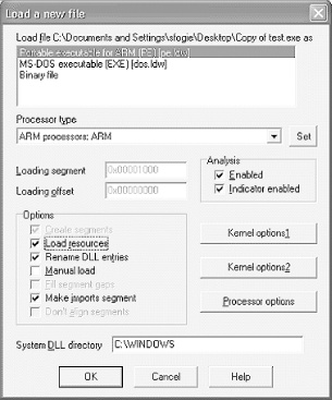
Check the “Load resources” box, change the “Processor type” drop-down menu selection to “ARM processors: ARM,” and click OK, as illustrated in Figure 4-6.
Click OK again if prompted to change the processor type.
Tip
At this point you may be asked for some *.dll files. We recommend that you find the requested files (either from MVT or from your device) and transfer them to a local folder on your PC. This allows IDA to fully disassemble the program. test.exe requires the AYGSHELL.DLL file, which can be downloaded from the Internet.
Locate any requested *.dll files and wait for IDA to disassemble the program.
If the Names window does not open, select it from the View → Open Subviews → Names menu.
Locate “LoadStringW” from the list and double-click on it.
At this point, you should have the following chunk of code listed at the top of the disassembler window:
.text:00011564 ;  S U B R O U T I N E
.text:00011564
.text:00011564
.text:00011564 LoadStringW   ; CODE XREF: sub_110E8+28#p
.text:00011564         ; sub_110E8+40#p ...
.text:00011564         LDR   R12, =_  _imp_LoadStringW
.text:00011568         LDR   PC, [R12]
.text:00011568 ; End of function LoadStringW
If you look at this code, you can see that LoadStringW is considered a subroutine . A subroutine is a mini-program that performs some action for the main program. In this case, it is loading a string. However, you will want to pay attention to the references that use this subroutine. These will be listed at the top of the routine under the CODE XREF, which stands for cross-reference. In our case, there are two addresses in this program that call this subroutine; they are sub_110E8+28 and sub_110E8+40. While these addresses may appear a bit cryptic, they are easy to understand. In short, the cross-reference sub_110E8+28 tells you that this LoadStringW subroutine was called by another subroutine that is located at address 110E8 in the program. The actual call to LoadStringW was made at the base 110E8 address plus 28 (hex) bytes of memory into the routine.
Tip
Not all XREFs are always visible. If there are more than two, there will be a “...” after the second reference.
While it is possible to scroll up to this memory location, IDA makes it easy by allowing us to click on the reference. Here’s the secret: right-click on the “...” and select the “Jump to cross reference” option. Select the third option on the list, which should be 1135C. Without this shortcut, you would have to go to each XREF and check to see where in the display process the code is.
Once at address 1135C, you can see that it looks very promising. Within a short chunk of code, you have several function calls that seem to be part of writing a message to a screen (i.e., BeginPaint, GetClientRect, LoadStringW, wcslen, DrawTextW). Now we will use the lessons we’ve learned to see what we can do.
As we learned, wcslen is a common point of weakness. We are going to use this knowledge to change the size of our message. Let’s take a closer look at this part of the code, assuming that the message is loaded into memory.
.text:0001135C          BL   LoadStringW       ;load string
.text:00011360          ADD   R0, SP, #0x54    ;change value of
                                               ;R0 to point to string location
.text:00011364          BL   wcslen            ;get length of
                                               ;string and put value in R0
.text:00011368    MOV   R3, #0x25              ;R3 = 0x25
.text:0001136C    MOV   R2, R0                 ;moves our string
                                               ;length into R2
.text:00011370    STR   R3, [SP]               ;pushes R3 value
                                               ;on memory stack
.text:00011374    ADD   R3, SP, #4             ;R3 = memory stack
                                               ;address + 4
.text:00011378    ADD   R1, SP, #0x54          ;R1 = memory stack
                                               ;address + 0x54
.text:0001137C    MOV   R0, R5                 ;moves R5 to R0
.text:00011380    BL   DrawTextW               ;writes text to
                                               ;screen using R0, R1, R2 to define
                                               ;location of string in memory,
                                               ;length of string, and type of draw.
Now that we have broken down this part of the code (which you will be able to do with practice), how can we change the length of the string that is drawn to the screen? Since we know that this value was moved into R2, we can assume that R2 is used by the DrawTextW routine to define the length. In other words, if we can control the value in R2, we can control the message on the screen.
To do this, we only need to change the assembler at address 1136C. Since R2 gets its value from R0, we can simply replace the R0 variable with a hardcoded value of our own. Now that we know this, let us edit the program using our hex editor.
Once you get the hex editor open, you will quickly see that the address in IDA does not match the address in the hex editor. However, IDA does provide the address in another part of the screen, as illustrated in Figure 4-7. The status bar located at the bottom left corner of the IDA window gives the actual memory location you need to edit.
Using the opcodes discussed previously in this chapter, you recreate the hex code you want to use in place of the existing code. The following is the original hex code and the code you will want to replace it with.
Here is the original:
MOV R2, R0 00 20 00 E1
And here it is, updated:
MOV R2, 1 01 20 00 E3
Note the change from E1 to E3; it differentiates between a MOV of a register value and a MOV of a hardcoded value.
What did this change accomplish? If you download the newest test.exe file to your PDA, you will see that it now has a message of just “H”. In other words, we caused the program to only load the first character of the message it had stored in memory. Now, imagine what we could do if we increased the size of the message to something greater than the message in memory. Using this type of trick, a cracker could perform all kinds of manipulation. However, these types of tricks often take more than just a disassembler, which is where MVT comes in handy.
Currently, there are very few tools available for live debugging of Windows CE devices. The choice of free tools is even more limited. However, Microsoft, in its benevolent wisdom, has provided just such a tool. You will need this tool to reverse engineer most Windows CE applications, unless you are intimately familiar with ARM assembler. Even if you do know the ARM code, the debugger will allow you to access parts of a program that you cannot access via a disassembler.
In short, MVT allows you to run a program, one line or opcode at a time. In addition, it allows you to observe the memory stack, register values, and values of variables in the program while it is executing. And if that isn’t enough, the debugger allows you to actually change the values of the registers and variables while the program is executing. With this power, you can change a Zero flag from a 1 to a 0 in order to bypass a protection check, or even watch the program compare an entered serial number with the hardcoded number, one character at a time. Needless to say, a debugger gives you total control over the program. It not only lets you look at the heart of its operation, but allows you to redesign a program on the fly.
To illustrate this power, we will use our little example program again. We will change the message on the screen, but this time we will locate the hardcoded message in memory and redirect the LDR opcode to a different point in the memory. This has the effect of allowing us to write whatever message we want to the screen, providing it exists in memory.
The first step in debugging a program is to load it into the MVT. This step typically involves the use of the Microsoft eMbedded Visual C++ (MVC) program that is included with the MVT package. Once C++ is open, perform the following steps to load the test.exe file into your debugger. Optionally, if you have a Windows Mobile device, you will want Microsoft ActiveSync loaded, with the device connected. In this case, be sure to have a copy of the test.exe file stored on the CE device, preferably under the root folder.
Open Microsoft eMbedded Visual C++.
Select File → Open.
Change “Files of type:” to “Executable Files” (.exe, .dll, .ocx).
Select the local copy of test.exe.
After brief delay, select Project → Settings from the top menu.
Click the Debug tab.
In the “Download directory:” text box, type “\” (or point the directory to the folder you have selected on the CE device).
Click OK, and then hit F11.
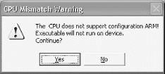
You will see a Connecting screen (Figure 4-8) followed by a warning screen (Figure 4-9). Select Yes on the CPU Mismatch Warning dialog window.

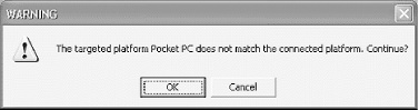
Click OK on the next warning screen (Figure 4-10).
The file will download and some file verification will occur.
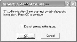
Click OK on the debugging information warning screen (Figure 4-11).
Once the program is loaded in debug mode, you will notice it is similar to IDA Pro. This is because the program must be disassembled before it can be executed in debug mode. As with any debugger, take a moment to become familiar with the tools and options available to you.
The Registers screen is one of the most useful, after the main Disassembly window. It is also important to note that you can change the conditional flags by double-clicking on their labels. This can easily turn an equal condition into an unequal condition, which will allow you to control the flow of the code.
The Call Stack windows provide a means of keeping track of the function in which you currently reside, as well as where the function will return if it is a BL. The Memory window allows you to look right into the RAM and the values it is holding. This is extremely valuable as a means to sniff out a serial number or value to which you want access. We demonstrate this process in our example.
When debugging a complicated program, you may also need to jump to determine where in memory a linked file exists. Doing so allows you to locate the code and set a breakpoint. Using the Modules window, you can easily find the memory range and jump to that point of code. In addition, pressing Alt-F9 allows you to set breakpoints (BPXs). Use breakpoints when you want to step into the address of a BL. MVC does not step into a BL; instead, it executes the code and jumps to the next line after the BL from the main function.
Now that you are familiar with the basic layout of the MVC, let’s try it out. For this example, we use the test.exe program, which you have already altered via the hex editor. Our goal is to use this program as a foundation, but we are going to once again alter the displayed text using some of the methods previously discussed. Although this example is simple, it allows you to become familiar with the embedded debugging environment.
The first thing we want to do is to jump to the point in the program where the message is displayed. Since we already found this using IDA Pro, we can easily jump to this part of the program. First, we need to know where in memory our test.exe program resides. We will use the Modules window. Once we open this window, we quickly see that the test.exe program is between 0x2E010000 and 0x2E015FFF. (Note that the first two characters may vary. It is important to interpret the following examples if your address does not match them exactly.) You may have noted that you are already sitting in this memory block, but using the Modules window is a good way to validate that you are in the correct section. Next, hit Alt-G to open the Goto window. Enter the address 2E01135C, which is based on the 2E value combined with the 0001135C address value we have deduced from early exploration.
Once you find that address, place a breakpoint next to it so the program will stop running at this point: either right-click on the memory address or hit Alt-F9. Make sure to enter the address with a 0x appended to the front. Without this hex declaration, the breakpoint will not set. If you are successful, you will see a red dot next to the address.
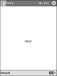
Now, hit the F5 key to execute the program. If all went well, the program stops at the address at which you placed the BPX. At this point in the execution, part of the program has executed. In fact, your Windows CE device may have the blank HACK window loaded on its screen (as shown in Figure 4-12). However, we are not yet at the place in the code where the actual message is written to the screen.
If you compare the disassembly screen in the MVT with that of the code in the IDA Pro hack we worked on previously, you can see we are at the key part of the code in which the message is written to the screen. However, unlike IDA Pro, the MVT does not provide the function names (e.g., 1135C is the LoadStringW function). This is one reason it is useful to have both programs open in tandem.
Once the program is paused at the BPX, you can see that the register values are all filled. Note that some are red and some are black. The red ones symbolize changes, making it easy to spot values that have been updated. As an example, hit the F11 key. The F11 key executes the BL code at 1135C, which in turn causes the R0-R3, R12, Lr, PC, and Psr values to change.
Since we know that the 1135C address pointed to a function that loaded the string, we can assume that the registers have been updated with this string’s information. This is in fact what has happened. R0 now equals C, which is the hex equivalent to the value 12. If you recall, the original message was 12 characters long. R1 also changed, and now holds the memory address of the string. To see the string, hit Alt-6 to open the Memory window. Once the window is open, type in the value held by R1 and hit Enter. This should cause the value TEST to appear at the top of the Memory window.
If you are wondering why our long 12-character string did not appear, you have to remember that memory is written to in reverse order: the value of the string ends at the address 2E015818. In other words, if you scroll up a few lines, you should see your message. So you now know that R2 points to the address in the program’s memory where the string is stored, and R0 holds the length of the string.
If we step through the program, we can see that the string is eventually added to the stack and is stored back into memory at 2E06FA60. During this process, the value in R0 is placed in R12, and R5’s value is placed in R0. There are some other value updates, but eventually, at 2E011380, the string is written to the screen.
During this process, note that address 11378 contained an add opcode that updated the value of R1 by adding Sp with 0x54. This is used to point to the place in temporary memory where the string is stored. So if we changed the 0x54 value to a value of our choosing, the output screen should reflect the change. To illustrate, let us look through the Memory window to see if we can find a different message. After scrolling down a bit, you should come to memory address 2E06FA10, which points to the beginning of the word HACK. Now that we have found an alternative message, how can we get this message to display?
This process is a matter of basic math. If our stack pointer is 6FA0C, to which 0x54 is added to point to the original message, we need to determine what value needs to be added to the stack pointer to point to our new address. In other words, 6FA60 - 0x54 = Sp, which means the original address is 6FA60. Using this equation, if the desired address is 6FDAC, then to figure out the difference we simply need to subtract the Sp from 6FDAC (i.e., 6FDAC - 6FA0C = 3A0).
At this point, we have determined the purpose of this hack. We have located a string in the memory that we wish to display and figured out the distance from the Sp to that memory address. We know that the opcode and assembler at address 11378 needs to be changed as follows.
Here’s the original:
ADD R1, SP, #0x54 54 10 8D E2
And here it is, updated:
ADD R1, SP, #0x3A0 3A 1E 8D E2
We also can use the lessons we previously learned to reduce the size of the string buffer to four characters. This would simply require us to change the instructions and assembler at 1136C as follows.
Here’s the original:
MOV R2, R0 00 20 00 E1
And the updated:
MOV R2, 1 01 20 00 E3
Once you have completed this exercise, save the new binary file and run it on MVT (or, optionally, upload it to your Windows CE device). If you got everything right, you should be rewarded with a screen similar to Figure 4-12.
Now that you’ve had a simple introduction to RCE on Windows CE, the next section provides a legal and hands-on tutorial of how to bypass serial protection. We describe multiple methods of circumvention of the protection scheme, which shows there’s more than one “right” way to do it. We use the previous discussion as a foundation.
For our example, we use our own program, called serial.exe. This program was written in Visual C++ to provide you with a real working product on which to test and practice your newly acquired knowledge. Our program simulates a simple serial number check that imitates those of many professional programs. You will see firsthand how a cracker can reverse engineer a program to allow any serial number, regardless of length or value. To obtain this embedded crackme, please download serial.exe from http://www.securitywarrior.com.
You must first load the target file into a disassembler from the local computer, using the steps we covered earlier. In this case, we are targeting a file called serial.exe, written solely for this example (Figure 4-13).
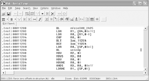
Once the program is open, drill down to a point in the program where you can monitor what is happening. As previously discussed, there are several function calls that flag an event worth inspection. For example, using the Names window, we can locate a wcscmp call, which is probably used to validate the entered serial number with the corrected serial number. Using this functions XREF, we can easily locate the chunk of code illustrated in Figure 4-13.
Since serial.exe is a relatively simple program, all the code we need to review and play with is located within a few lines. They are as follows:
.text:00011224             MOV   R4, R0
.text:00011228             ADD   R0, SP, #0xC
.text:0001122C             BL   CString::CString(void)
.text:00011230             ADD   R0, SP, #8
.text:00011234             BL   CString::CString(void)
.text:00011238             ADD   R0, SP, #4
.text:0001123C             BL   CString::CString(void)
.text:00011240             ADD   R0, SP, #0x10
.text:00011244             BL   CString::CString(void)
.text:00011248             ADD   R0, SP, #0
.text:0001124C             BL   CString::CString(void)
.text:00011250             LDR   R1, =unk_131A4
.text:00011254             ADD   R0, SP, #0xC
.text:00011258             BL   CString::operator=(ushort)
.text:0001125C             LDR   R1, =unk_131B0
.text:00011260             ADD   R0, SP, #8
.text:00011264             BL   CString::operator=(ushort)
.text:00011268             LDR   R1, =unk_131E0
.text:0001126C             ADD   R0, SP, #4
.text:00011270             BL   ; CString::operator=(ushort)
.text:00011274             LDR   R1, =unk_1321C
.text:00011278             ADD   R0, SP, #0
.text:0001127C             BL   CString::operator=(ushort)
.text:00011280             MOV   R1, #1
.text:00011284             MOV   R0, R4
.text:00011288             BL   CWnd::UpdateData(int)
.text:0001128C             LDR   R1, [R4,#0x7C]
.text:00011290             LDR   R0, [R1,#-8]
.text:00011294             CMP   R0, #8
.text:00011298             BLT   loc_112E4
.text:0001129C             BGT   loc_112E4
.text:000112A0             LDR   R0, [SP,#0xC]
.text:000112A4             BL   wcscmp
.text:000112A8             MOV   R2, #0
.text:000112AC             MOVS  R3, R0
.text:000112B0             MOV   R0, #1
.text:000112B4             MOVNE  R0, #0
.text:000112B8             ANDS  R3, R0, #0xFF
.text:000112BC             LDRNE  R1, [SP,#8]
.text:000112C0             MOV   R0, R4
.text:000112C4             MOV   R3, #0
.text:000112C8             BNE   loc_112F4
.text:000112CC             LDR   R1, [SP,#4]
.text:000112D0             B    loc_112F4
.text:000112E4
.text:000112E4 loc_112E4                ; CODE XREF: .text:00011298
.text:000112E4                          ; .text:0001129C
.text:000112E4             LDR   R1, [SP]
.text:000112E8             MOV   R3, #0
.text:000112EC             MOV   R2, #0
.text:000112F0             MOV   R0, R4
.text:000112F4
.text:000112F4 loc_112F4                ; CODE XREF: .text:000112C8
.text:000112F4                          ; .text:000112D0
.text:000112F4             BL   CWnd_  _MessageBoxW
If you have not touched anything after IDA placed you at address 0x000112A4, then that line should be highlighted blue. If you want to go back to the last address, use the back arrow at the top of the window or hit the Esc key.
Since we want to show you several tricks crackers use when extracting or bypassing protection, let’s start by considering what we are viewing. At first glance at the top of our code, you can see there is a pattern. A string value appears to be loaded in from program data, and then a function is called that does something with that value. If we double-click on unk_131A4, we can see what the first value is “12345678”, or our serial number. While our serial.exe example is simplified, the fact remains that any data used in a program’s validation must be loaded in from the actual program data and stored in RAM. As our example illustrates, it doesn’t take much to discover a plain text serial number. In addition, it should be noted that any hex editor can be used to find this value, although it may be difficult to parse out a serial number from the many other character strings that are revealed in a hex editor.
As a result of this plain text problem, many programmers build an algorithm into the program that deciphers the serial number as it is read in from memory. It’s typically indicated by a BL to the memory address in the program that handles the encryption/algorithm. An example of another method of protection is to use the device owner’s name or some other value to dynamically build a serial number. This completely avoids the problems, surrounding and storing it within the program file, and indirectly adds an extra layer of protection on to the program. Despite efforts to create complex and advanced serial number creation schemes, the simple switch of a 1 to a 0 can nullify many antipiracy algorithms, as you will see.
The remaining code from 0x00011250 to 0x0001127C is also used to load values from program data to the device’s RAM. If you check the values at the address references, you can quickly see that three messages are loaded into memory as well. One is a “Correct serial” message, and the other two are “Incorrect serial” messages. Knowing that there are two different messages is a minor but important tidbit of information, because it tells us that failure occurs in stages or as a result of two different checks.
Moving through the code, we see that R1 is loaded with some
value out of memory, which is used to load another value into R0.
After this, in address 0x00011294, we can see that R0 is compared
to the number eight (CMP
R0, #8). The next two lines check the result
of the comparison, and if it is greater than or less than eight,
the program jumps to loc_112E4 and continues from there.
If we follow loc_112E4 in IDA Pro, it starts to get a bit more difficult to determine what is happening, which brings us to the second phase of the reverse engineering process: the live debugger.
As we illustrated when debugging test.exe, the MVT is a very useful tool that can help a debugger, or a cracker, work through a program’s execution line by line. This type of intimate relationship allows an in-depth look at the values being processed and can also allow on-the-fly alteration of data that is stored in the registers, flags, and memory.
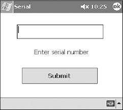
After the program is loaded, set a breakpoint at 0x00011280, with any changes as defined by the absolute memory block. Once the breakpoint is entered, hit the F5 key to execute the program. You should now see a Serial screen on your Pocket PC as in Figure 4-14. Enter any value in the text box and hit the Submit button.
After you click the Submit button, your PC should shift focus to the section of code we looked at earlier in IDA. Notice the little yellow arrow on the left side of the window, pointing to the address of the breakpoint. Right-click on the memory address column and note the menu that appears. You will use this menu quite frequently when debugging a program.
Tip
The MVT is slow in execution mode when it’s using a USB/serial connection. If you are in the habit of jumping between programs, you will quickly become frustrated at the time required for the MVT to redraw the screen. To avoid these delays, ensure the MVT is in break mode before changing window focus.
At this point, serial.exe is
loaded on the Pocket PC and the MVT is paused at a breakpoint. The
next command the processor executes MOV R1,
#1. This is a simple command to
move the value 1 into register 1 (R1).
Before executing this line, look at the Registers window and note the value of R1. You should also note that all the register values are red; this is because they have all changed from the last time the program was paused. Now, hit the F11 key to execute the next line of code. After a short pause, the MVT returns to pause mode, at which time you should notice several things. The first is that most of the register values turned to black, which means they did not change values. The second is that R1 now equals 1.
The next line loads the R0 register with the value in R4. Once again, hit the F11 key to let the program execute this line of code. After a brief pause, you will see that R0 is equal to R4. Step through a few more lines of code until your yellow arrow is at address 0x00011290. At this point, let’s take a look at the Registers window.
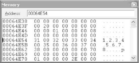
The last line of code executed was an LDR command that loaded a value (or address representing the value) from memory into a register. In this case, the value was loaded into R1, which should be equal to 0006501C. Locate the Memory window and enter the address stored by R1 into the “Address:” box. Once you hit Enter, you should see the serial number you entered.
After executing the next line, we can see that R0 is given a small integer value. Take a second and see if you can determine its significance. In R0, you should have a value equal to the number of characters in the serial you entered. In other words, if you entered “777”, the value of R0 should be 3, which represents the number of characters you entered.
The next line, CMP R0, #8,
is a simple comparison opcode. When this opcode is executed, it will
compare the value in R0 with the integer 8. Depending on the results
of the comparison, the status flags will be updated. These flags are
conveniently located at the bottom of the Registers window. Note
their values and hit the F11 key. If the values change to N1 Z0 C0
O0, your serial number is not 8 characters long.
At this point, serial.exe is headed for a
failure message (unless you happened to enter eight characters). The
next two lines of code use the results of the CMP to determine if
the value is greater than or equal to eight. If either is true, the
program jumps to address 0x000112E4, where a message will be
displayed on the screen. If you follow the code, you will see that
address 0x000112E4 contains the opcode LDR R1,
[SP]. If you follow this through
and check the memory address after this line executes, you will see
that it points to the start of the following error message at
address 0x00065014: “Incorrect serial number. Please verify it was
typed correctly.”
Now that we know the details of the first check, we want to
break the execution and restart the entire program. Perform the same
steps that you previously worked through, but set a breakpoint at
address 0x00011294 (CMP R0, #8). Once the program is paused at the CMP
opcode, locate the Registers window and note the value of R0. Now,
place your cursor on the value and overwrite it with “00000008”.
This very handy function of the MVT allows you to trick the program
into thinking your serial is eight characters long, thus allowing
you to bypass the check. While this works temporarily, we will need
to make a permanent change to the program to ensure any value is
acceptable at a later point.
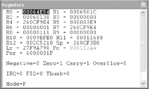
After the change is made, use the F11 key to watch serial.exe execute through the next few lines of code. Then, continue until the pointer is at address 0x000112A4 (BL 00011754). While this command may not mean much to you in the MVT, if we jump back over to IDA Pro we can see that this is a function call to wcscmp, which is where our serial is compared to the correct serial. Knowing this, we should be able to take a look at the Registers window and determine the correct serial.
Tip
Function calls that require data to perform their operations use the values held by the registers. In other words, wcscmp will compare the values of R0 with the value of R1, which means we can easily determine what these values are. It then returns a true or false in R1.
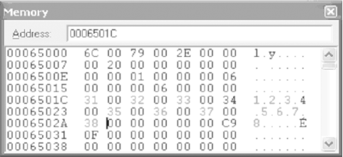
If we look at R0 and R1, we can see that they hold the values 00064E54 and 0006501C, respectively, as illustrated by Figure 4-15 (these values may be different for your system). While these values are not the actual serial numbers, they do represent the locations in memory where the two serials are located. To verify this, place R1’s value in the Memory window’s “Address:” field and hit Enter. After a short pause, the Memory window should change, and you should see the serial number you entered. Next, do the same with the value held in R0. This will cause your Memory window to change to a screen similar to Figure 4-16, in which you should see the value “1.2.3.4.5.6.7.8”—in other words, the correct serial.
At this point, a cracker could stop and simply enter the newfound value to gain full access to the target program, and he could also spread the serial number around on the Internet. However, many serial validations include some form of dynamically generated serial number (based on time, name, or a matching registration key), which means any value determined by viewing it in memory will only work for that local machine. As a result, crackers often note the serial number and continue on to determine where the program can be “patched” in order to bypass the protection, regardless of the dynamic serial number.
Moving on through the program, we know the wcscmp function will compare the values held in memory, which results in an update to the condition flags and R0-R4, as follows:
- R0
If the serials are equal, R0 = 0; else R0 = 1.
- R1
If equal, address following entered serial number; else, address of failed character.
- R2
If equal, R2 = 0; else, hex value of failed character.
- R3
If equal, R3 = 0; else, hex value of correct character.
We need to once again trick the program into believing it has the right serial number. This can be done one of two ways. The first method is to actually update your serial number in memory. To do this, note the hex values of the correct serial (i.e., 31 00 32 00 33 00 34 00 35 00 36 00 37 00 38), and overwrite the entered serial number in the Memory window. When you are done, your Memory window should look like Figure 4-17.
The second method a cracker can use is to update the condition flags after the wcscmp function has updated the status flags. To do this, hit F11 until the pointer is at 0x000112A8. You should note that the Z condition flags change from 1 (equal) to 0 (not equal). However, if you don’t like this condition, you can change the flags back to their original values by overwriting them. Once you do this, the program will once again think the correct serial number was entered. While this temporarily fixes the serial check, a lasting solution requires an update to the program’s code.
Fortunately, we do not have to look far to find a weak point. The following explains the rest of the code that is processed until a message is provided on the Pocket PC, alerting the user to a correct (or incorrect) serial number.
This opcode clears out the R2 register so there are no remaining values that could confuse future operations:
260112A8 mov r2, #0
In the next opcode, two events occur. The first is that R0 is moved into R3. The second event updates the status flags using the new value in R3. As we previously mentioned, R0 is updated from the wcscmp function. If the entered serial number matched the correct serial number, R0 will be updated with a 0. If they didn’t match, R0 will be set to 1. R3 is then updated with this value and checked to see if it is negative or zero.
260112AC movs r3, r0 Moves R0 into R3 and updates the status flags
Next, the value #1 is moved into R0. This may seem a bit odd, but by moving #1 into R0, the program is setting the stage for the next couple of lines of code.
260112B0 mov r0, #1 Move #1 into R0
Next, we see another altered MOV command. In this case, the value #0 will be moved into R0 only if the condition flags are not equal (ne), which is based on the status update performed by the previous MOV. In other words, if the serials matched, R0 would have been set to 0 and the Zero flag would have been set to 1, which means the MOVNE opcode would not be executed.
260112B4 movne r0, #0 If flags are not equal, move #0 into R0
Like the MOV opcode, the ANDS command first executes and then updates the status flags depending on the result. Looking at the last few lines, we can see that R0 should be 1 if the serials did not match. This is because R0 was set to equal #1 a few lines up and was not changed by the MOVNE opcode. Therefore, the AND opcode would result in R3 being set to the value of #1, and the condition flags would be updated to reflect the “equal” status. On the other hand, if the serials did match, R0 would be equal to 1, which would have caused the Zero flag to be set to 0, or “not equal.”
260112B8 ands r3, r0, 0xFF
Next, we see another implementation of the “not equal” conditional opcode. In this case, if the ANDS opcode set the Z flag to 0—which would occur only if the string check passed—the LDRNE opcode would load R1 with the data in SP+8. Recall from our dissection of code in IDA Pro that address 0x0001125C loaded the “correct message” into this memory location. However, if the condition flags are not set at “not equal” or “not zero,” this opcode will be skipped.
260112BC ldrne r1, [sp, #8]
This is an example of a straightforward move of R4 into R0:
260112C0 mov r0, r4 Move R4 into R0
This is another example of a simple move of #0 to R3:
260112C4 mov r3, #0 Move #0 into R3
Again, we see a conditional opcode. In this case, the program will branch to 0x000112F4 if the “not equal” flag is set. Since the conditional flags have not been updated since the ANDS opcode in address 0x000112B8, a correct serial number would result in the execution of this opcode.
260112C8 bne 260112F4 ; If flag not equal jump to 0x260112F4
If the wrong eight-character serial number was entered, this line would load the “incorrect” message from memory into R1:
260112CC ldr r1, [sp, #4] Load SP+4 into R1 (incorrect message)
This line tells the program to branch to address 0x260112F4:
260112D0 b 260112F4 ; Jump to 0x260112F4
The final line we will look at is the call to the MessageBoxW function. This command simply takes the value in R1, which will either be the correct message or the incorrect message, and displays it in a message box.
...
260112F4  bl    26011718 ;       MessageBoxW call to display message in R1
Now that we have dissected the code, we must alter it to ensure that it will accept any serial number as the correct value. As we have illustrated, when executing the program in the MVT, we can crack the serial fairly easily by changing the register values, memory, or condition flags during program execution. However, this type of legerdemain is not going to help the average user who has no interest in reverse engineering. As a result, a cracker will have to make permanent changes to the code to ensure the serial validation will always validate the entered serial.
To do this, the cracker has to find a weak point in the code that can be changed in order to bypass security checks. Fortunately for the cracker, there is typically more than one method by which a program can be cracked. To illustrate, we demonstrate three distinct ways that serial.exe can be cracked using basic techniques.
The first method requires three separate changes to the code. The first change is at address 00011294, where R0 is compared to the value #8. If you recall, this is used to ensure that the user-provided serial number is exactly eight characters long. The comparison then updates the condition flags, which are used in the next couple of lines to determine the flow of the program.
To ensure that the flags are set at “equal,” we need to
alter the compared values. The easiest way to do this is to have
the program compare two equal values (i.e., CMP R0,
R0). This ensures the comparison returns as “equal,”
thus tricking the program into passing over the BLT and BGT
opcodes in the next two lines.
The next change is at address 0x000112B4, where we find a
MOVNE R0, #0 command. As we previously discussed,
this command checks the flag conditions, and if they are set at
“not equal,” the opcode moves the value #0 into R0. The R0 value
is then checked when it is moved into R3, which updates the status
flags once again.
Since the MOVS command at address 00112AC will set Z = 0
(unless the correct serial is entered), the MOVNE opcode will then
execute, thus triggering a chain of events that results in a
failed validation. To correct this, we need to ensure the program
thinks R0 is always equal to #1 at line 000112B8 (ANDS R3, R0, #0xFF). Since R0 would have been changed
to #1 in address 000112B0 (MOV
R0, #1), the ANDS opcode would result in a
“not equal” for a correct serial.
In other words, we need to change MOVNE R0, #0 to MOVNE R0, #1 to ensure that R0 AND FF outputs 1, which is then used to
update the status flags. The program will thus be tricked into
validating the incorrect serial.
Here are the changes:
.text:00011294         CMP   R0, #8 -> CMP R0, R0
.text:000112B4         MOVNE  R0, #0 -> MOVNE R0,#1
Determining the necessary changes is the first step to cracking a program. The second step is to actually alter the file. To do this, a cracker uses a hex editor to make changes to the actual .exe file. However, in order to do this, the cracker must know where in the program file she needs to make changes. Fortunately, if she is using IDA Pro, a cracker only has to click on the line she wants to edit and look at the status bar at the bottom of IDA’s window, as we previously discussed. As Figure 4-18 illustrates, IDA clearly displays the memory address of the currently selected line, which can then be used in a hex editor.
Once we know the addresses where we want to make our changes, we will need to determine the values with which we want to update the original hex code. (Fortunately, there are several online reference guides that can help.) We want to make the changes shown in Table 4-4 to the serial.exe file.
Table 4-4. Changes to serial.exe
IDA address | Hex address | Original opcode | Original hex | New opcode | New hex |
|---|---|---|---|---|---|
0x11294 | 0x694 | CMP: R0, #8 | 08 00 50 E3 | CMP R0, R0 | 00 00 50 E1 |
0x112B4 | 0x6B4 | MOVNE R0, #0 | 00 00 A0 13 | MOVNE R0, #1 | 01 00 A0 13 |
To make the changes, perform the following procedures (using UltraEdit).
Open UltraEdit and then open your local serial.exe file in UltraEdit.
Using the left-most column, locate the desired hex address.
Move to the hex code that needs to be changed, and overwrite it.
Save the file as a new file, in case you made a mistake.
The next example uses some of the same tactics as Crack 1, but it also introduces a new method of bypassing the eight-character validation, known as NOP.
The term NOP is a reference to a nonoperation, which means the code is basically null. Many crackers and hackers are familiar with the term NOP due to its prevalence in buffer overflow attacks. In buffer overflows, a NOP slide (as it is often called) is used to make a part of the program do absolutely nothing. The same NOP slide can be used when bypassing a security check in a program.
In our program, we have a CMP opcode that compares the length of the entered serial with the number 8. This results in a status change of the condition flags, which are used by the next two lines to determine if they are executed. While our previous crack bypassed this by ensuring the flags were set at “equal,” we can attack the BLT and BGT opcodes by overwriting them with a NOP opcode. Once we do this, the BLT and BGT opcodes no longer exist.
Warning
Typical x86 NOPing is done using a series of 0x90s. This
will not work on an ARM processor and will
result in the following opcode: UMULLLSS R9, R0, R0, R0. This opcode actually performs an
unsigned multiply long if the LS condition is met, and then
updates the status flags accordingly. It is not a NOP.
The trick we learned to perform a NOP on an ARM processor is
to simply replace the target code with a MOV R1, R1 operation. This will move the value
R1 into R1 and will not update the status flags. The following
code illustrates the NOPing of these opcodes.
.text:00011298         BLT   loc_112E4 -> MOV R1, R1
.text:0001129C         BGT   loc_112E4 -> MOV R1, R1
The second part of this crack was already explained in Crack 1 and requires only the alteration of the MOVNE opcode, as the following portrays:
.text:000112B4 MOVNE R0, #0 -> MOVNE R0,#1
Table 4-5 describes the changes you will have to make in your hex editor.
At this point you are probably wondering what the point of another example is when you already have two crack methods that work just fine. However, we have saved the best example for last—Crack 3 does not attack or overwrite any checks or validation opcodes, like our previous two examples. Instead, it demonstrates how to alter the registers to our benefit before any values are compared.
If you examine the opcode at 0x00001128C using the MVT, you will see that it sets R1 to the address of the serial that you entered. The length of the serial is then loaded into R0 in the next line, using R1 as the input variable. If the value pointed to by the address in R1 is eight characters long, it is then bumped up against the correct serial number in the wcscmp function. Knowing all this, we can see that the value loaded into R1 is a key piece of data. So, what if we could change the value in R1 to something more agreeable to the program, such as the correct serial?
While this is possible by using the stack pointer to guide us, the groundwork has already been done in 0x0000112A0, where the correct value is loaded into R0. Logic assumes that if it can be loaded into R0 using the provided LDR command, then we can use the same command to load the correct serial into R1. This would trick our validation algorithm into comparing the correct serial with itself, which would always result in a successful match!
The details of the required changes are as shown in Table 4-6.
Table 4-6. Changes to serial.exe for Crack 3
IDA address | Hex address | Original opcode | Original hex | New opcode | New hex |
|---|---|---|---|---|---|
0x11298 | 0x68C | LDR R1, [R4, #0x7C] | 7C 10 94 E5 | LDR R1, [SP,#0xC] | 0C 10 9D E5 |
Note that this crack only requires the changing of two hex characters (i.e., 7 → 0 and 4 → D). This example is by far the most elegant and foolproof of the three, which is why we saved it for last. While the other two examples are just as effective, they are each a reactive type of crack that attempts to fix a problem. This crack, on the other hand, is a preventative crack that corrects the problem before it becomes one.
An extensive library of CE reversing tutorials. (http://www.ka0s.net)
Useful information on the ARM processor. (http://www.arm.com)
Background for learning ASM. (http://www.heyrick.co.uk/assembler/)
Download useful tools such as the MVT (http://www.microsoft.com/windows/embedded/default.asp)
Detailed information on the CE kernel. (http://msdn.microsoft.com/library/en-us/wcekern/htm/_wcesdk_kernel_services.asp)
“Embedded reverse engineering,” by Seth Fogie, Airscanner Corp. Paper presented at Defcon 11, August 2003.
[1] When a call is made to another function, the value of the PC register (the current address location) needs to be stored in the Lr (14) register in order to hold the address from which BL instruction will return.
[2] When reversing, you need a way to create nonoperations. While you can use the 90 NOP slide, moving the value of a register into itself produces the same results. Nothing is updated and no flags are changed when this operation is executed.
Get Security Warrior now with the O’Reilly learning platform.
O’Reilly members experience books, live events, courses curated by job role, and more from O’Reilly and nearly 200 top publishers.

