June 2014
Intermediate to advanced
176 pages
3h 43m
English
The phenomenon of reflection that arises at the junction between two circuits during the propagation of high-speed signals is the source of the deterioration in signal quality, particularly for clock signals. The concept of controlled impedance must be used in specific circuits in order to avoid these reflections and enhance circuit performance.
With harmonic signals, propagation phenomena appear in circuits when the dimensions are larger than one-tenth of the wavelength. During a propagation with a given effective permittivity, the wavelength is defined by relationship [3.1].
[3.1] 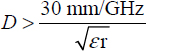
The insulating materials used in interconnects have a relative permittivity between 1 and 10 (see Table 3.1). Thus, for a frequency equal to 1 GHz, the wavelength in interconnects is included between 100 mm and in the time domain. Propagation becomes critical when the delay caused by it is greater than the rise time. From this condition, the circuits are referred to as “distributed” and reflection phenomena must be taken into account.
Let us consider a link between two logic circuits according to Figure 3.1.
Table 3.1. Relative permittivity of some materials [ANS 13]
| Material | Relative permittivity (εr) | Loss angle (tanδ) |
| Air | 1 | 0 |
| Aluminum oxide 96 | 9.4 | 0.006 |
| Arlon 25FR | 3.43 | 0.0035 |
| Arlon AR450 |
Read now
Unlock full access


