12.2 Structure and Operation of AWGs
We shall first describe the construction of an AWG and describe its basic working principle [8–12].
12.2.1 Structure and Working Principle
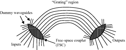
AWGs are the most important PHASAR device and are alternatively called WGRs. The principle of operation of the device may be understood with the help of Figure 12.1. The structure is symmetric, and either side could be input or output.
Figure 12.1 Structure of an arrayed waveguide grating (AWG).

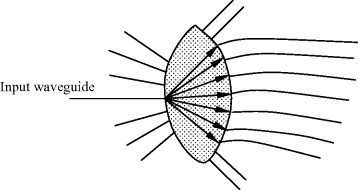
The input and output stages consist of star couplers called free space couplers (FSCs), also referred to as slab regions. The two FSCs are interconnected by the grating region consisting of an array of channel waveguides having different lengths and having no coupling with one another. When a single-mode signal is fed to one of the input waveguides, it couples to a large number of modes in FSC and then couples to the arrayed waveguides, as shown in Figure 12.2. The power coupled from any particular input to each of the arrayed waveguide is equal, but due to difference in lengths, the light in each waveguide will differ in phase.
Figure 12.2 Coupling of a signal to the input of all waveguides in the AWG via FSC.

The length of each channel guide differs from its neighbors by a fixed amount ΔL. This results in further ...
Get Silicon Photonics: Fundamentals and Devices now with the O’Reilly learning platform.
O’Reilly members experience books, live events, courses curated by job role, and more from O’Reilly and nearly 200 top publishers.

