6.6 Example LCD Display Setup Program
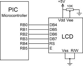
An example C program is given here to show how the LCD can be set up. The connection of the LCD to the microcontroller is shown in Figure 6.9 (if you are using the EasyPIC 7 development board, all you have to do is just connect the LCD to the board). PORT B lower pins (RB0 to RB3) are connected to the upper 4 bits of the LCD (DB4 to DB7). In addition, RB4 and RB5 pins are connected to LCD RS and E pins, respectively.
Figure 6.9 Connecting the LCD to a PIC microcontroller

The program listing is shown in Figure 6.10. The following functions are used in the program:
The LCD setup functions are ...
Get Using LEDs, LCDs and GLCDs in Microcontroller Projects now with the O’Reilly learning platform.
O’Reilly members experience books, live events, courses curated by job role, and more from O’Reilly and nearly 200 top publishers.

