9.1 PROJECT 9.1 – Flashing LED
9.1.1 Project Description
This is perhaps the simplest project we can have. In this project, an LED is connected to bit 0 of PORT C (RC0) of a PIC18F45K22 type microcontroller (other PIC microcontrollers can also be used). The reason for using this microcontroller is because the EasyPIC 7 development board is equipped with this type of PIC microcontroller), operated from an 8 MHz crystal. The LED is flashed with 1 second intervals.
As described in Section 5.1, an LED is connected to a microcontroller using a current limiting resistor. An LED can be connected in two modes to a microcontroller output port: current sinking mode or current sourcing mode.
9.1.1.1 Current Sinking Mode
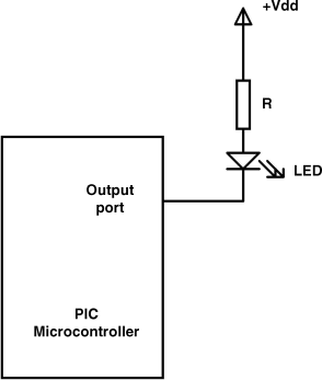
As shown in Figure 9.1, in current sinking mode the cathode of the LED is connected to the microcontroller I/O port, while the anode is connected to +5 V supply through a current limiting resistor. Here, the LED is turned ON when the output of the microcontroller is at logic LOW, where current flows into the microcontroller pin. The output current sink capability of each PIC microcontroller I/O pin is 25 mA. As was shown in Section 5.1, a 330 ohm or smaller resistor should give a current of about 10 mA, which is sufficient to drive the LED to give bright light.
Figure 9.1 LED connected in current sinking mode

9.1.1.2 Current Sourcing Mode
As shown in Figure 9.2, in current ...
Get Using LEDs, LCDs and GLCDs in Microcontroller Projects now with the O’Reilly learning platform.
O’Reilly members experience books, live events, courses curated by job role, and more from O’Reilly and nearly 200 top publishers.

