9.3 PROJECT 9.3 – Rotating LEDs
9.3.1 Project Description
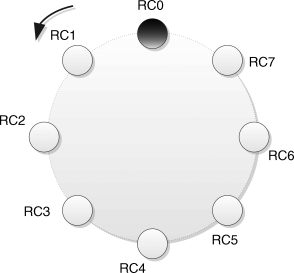
In this project, 8 LEDs are connected to PORT C of a PIC microcontroller as in Project 2. The LEDs turn ON right to left (bit 0 towards bit 7) in a rotating manner, with a 1 second delay between each output where only one LED is ON at any time. If the LEDs are arranged in a circular way, the pattern displayed by the LEDs will be as shows in Figure 9.16.
Figure 9.16 Rotating LEDs

9.3.2 Block Diagram
The block diagram of the project is as shown in Figure 9.12.
9.3.3 Circuit Diagram
The circuit diagram of the project is as shown in Figure 9.13.
9.3.4 Project PDL
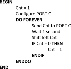
The PDL of this project is very simple and is given in Figure 9.17.
Figure 9.17 PDL of the project

9.3.5 Project Program
The program is named LED5.C and the program listing of the project is given in Figure 9.18. At the beginning of the project, variable Cnt is initialised to 1. PORT C is configured as a digital I/O port as before. An endless for loop is then constructed and Cnt is sent to PORT C. After a 1 second delay, Cnt is shifted left and the loop is repeated forever. Thus, Cnt takes the values 1 2 4 8 16 32 64 128 1 2 . . .
9.3.6 Modification of the Program
The program given in Figure 9.18 rotates the LEDs left. Now we will modify the program so that the LEDs ...
Get Using LEDs, LCDs and GLCDs in Microcontroller Projects now with the O’Reilly learning platform.
O’Reilly members experience books, live events, courses curated by job role, and more from O’Reilly and nearly 200 top publishers.

