10.3 PROJECT 10.3 – Display Lottery Numbers on 2-Digit 7-Segment LED Display
10.3.1 Project Description
In this project, a 2-digit 7-segment display is connected to PORT D of the microcontroller. The project displays 7 random lottery numbers between 1 and 49 with a 5-second interval between each number. The last number displayed is considered to be the ‘bonus’. A push-button switch is used to start the game. At the end of displaying all the 7 numbers, the display goes blank to indicate that the circuit is ready to start a new game.
In this project, the displays are refreshed inside a timer interrupt service routine in the background, so that the processor is free to do other tasks.
10.3.2 Block Diagram
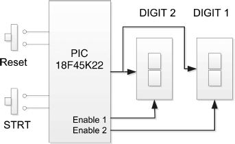
The block diagram of the project is shown in Figure 10.11. The 2-digit display pins a–g are connected in parallel and each digit is controlled separately. The push-button switch STRT starts the game.
Figure 10.11 Block diagram of the project

10.3.3 Circuit Diagram
The circuit diagram of the project is shown in Figure 10.12. The displays are connected in parallel to PORT D of the microcontroller. Each digit is enabled separately by connecting a transistor as a switch to its common cathode pin, as in the earlier project. Setting the base of the transistor to logic HIGH turns the transistor ON and enables the display. PORT A pins RA0 and RA1 are used to control the display enable lines. ...
Get Using LEDs, LCDs and GLCDs in Microcontroller Projects now with the O’Reilly learning platform.
O’Reilly members experience books, live events, courses curated by job role, and more from O’Reilly and nearly 200 top publishers.

