13.2 PROJECT 13.2 – LED Flashing with Variable Rate
13.2.1 Project Description
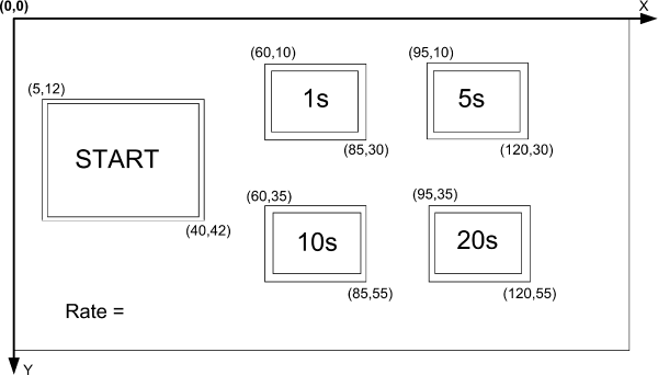
This project shows how the GLCD and touch screen can be used to develop the project of a flashing LED, where the flashing rate is selected by touching the appropriate button on the GLCDscreen. Figure 13.10 shows the screen layout and co-ordinates of the various boxes and rectangles displayed on the screen.
Figure 13.10 Screen layout of the project

An LED is connected to pin RC7 of the microcontroller. The flashing rate is displayed on the screen in the form of boxes. Four options are available: 1 second, 5 seconds, 10 seconds and 20 seconds. The user initially selects the flashing rate by touching the required box on the screen. The flashing then starts by touching the START button.
13.2.2 Block Diagram
The block diagram of the project is as shown in Figure 13.3.
13.2.3 Circuit Diagram
The circuit diagram of the project is as shown in Figure 13.5.
13.2.4 Project PDL
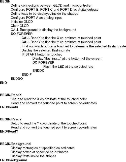
The PDL of this project is given in Figure 13.11.
Figure 13.11 PDL of the project

13.2.5 Project Program
The program is named TScreen2.C and the program listing of the project is shown in Figure 13.12. At the beginning of the project, an LED is assigned to port pin RC7 of the microcontroller. Then, the connections between the microcontroller ...
Get Using LEDs, LCDs and GLCDs in Microcontroller Projects now with the O’Reilly learning platform.
O’Reilly members experience books, live events, courses curated by job role, and more from O’Reilly and nearly 200 top publishers.

