15.1 PROJECT 15.1 – Countdown Timer
15.1.1 Project Description
This project describes the design of a countdown timer using the MikroMMB board for PIC18FJ (from now onwards, this board will be called the MikroMMB board). The screen consists of a soft keypad with numbers 0 to 9, a START button, a CLR button and a display box. The operation of the project is as follows: the user enters a starting number and clicks the START button. The display counts down in 1 second intervals until the count reaches zero and then it stops. Clicking the CLR button clears the display and the system is ready for the next count.
15.1.2 Block Diagram
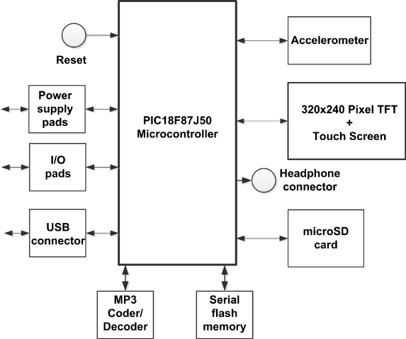
The block diagram of the MikroMMB board is shown in Figure 15.1. A detailed circuit diagram can be obtained from the manufacturer's product guide.
Figure 15.1 Block diagram of the MikroMMB board

The steps for creating this project are given below:
15.1.2.1 General (see Figure 15.2)
- Hardware patterns: MikroMMB_for_PIC18FJ_hw_rev_1.05;
- Target Compiler: mikroC Pro for PIC PRO for PIC;
- Target Device: PIC18F87J50;
- Device Clock (Hz): 48 000 000.
Get Using LEDs, LCDs and GLCDs in Microcontroller Projects now with the O’Reilly learning platform.
O’Reilly members experience books, live events, courses curated by job role, and more from O’Reilly and nearly 200 top publishers.

