4.1 INTRODUCTION
Retiming [1] is a transformation technique used to change the locations of delay elements in a circuit without affecting the input/output characteristics of the circuit. For example, consider the IIR filter in Fig. 4.1(a). This filter is described by
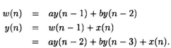
The filter in Fig. 4.1 (b) is described by
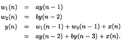
Although the filters in Fig. 4.1(a) and Fig. 4.1(b) have delays at different locations, these filters have the same input/output characteristics. These 2 filters can be derived from one another using retiming.
Retiming has many applications in synchronous circuit design. These applications include reducing the clock period of the circuit, reducing the number of registers in the circuit, reducing the power consumption of the circuit, and logic synthesis. The topics of retiming to reduce the clock period and to reduce the number of registers are discussed in detail in this chapter. Retiming for logic synthesis is beyond the scope of this book.
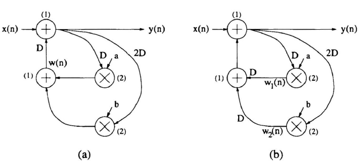
Fig. 4.1 Two versions of an IIR filter. The computation times of the nodes are shown in parentheses.
Retiming can be used to increase the clock rate of a circuit by reducing the computation time of the critical path. Recall that the ...
Get VLSI Digital Signal Processing Systems: Design and Implementation now with the O’Reilly learning platform.
O’Reilly members experience books, live events, courses curated by job role, and more from O’Reilly and nearly 200 top publishers.

